- Catalogs
- RIFTEK EUROPE
- Width Measurement System RF590 Manual
- Company
- Products
- Catalogs
- News & Trends
- Exhibitions
Width Measurement System RF590 Manual
1 /21Pages

Width Measurement System RF590 Manual
1 /21Pages
Catalog excerpts
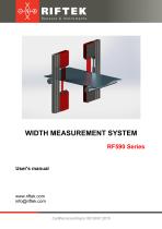
WIDTH MEASUREMENT SYSTEM RF590 Series User's manual www.riftek.com [email protected]
Open the catalog to page 1
Width Measurement System. RF590 Series
Open the catalog to page 2
Width Measurement System. RF590 Series Safety precautions · · · · Use supply voltage and interfaces indicated in the system specifications. In connection/disconnection of cables, the system power must be switched off. Do not use the system in locations close to powerful light sources. To obtain stable results, wait about 20 minutes after sensor activation to achieve uniform sensor warm-up. · The indication device must be grounded and connected to the grounding bus by a separate branch. The system has been developed for use in industry and meets the requirements of the following Directives: ·...
Open the catalog to page 3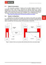
Width Measurement System. RF590 Series Optical micrometers The micrometer operation is based on the so-called ‘shadow’ principle. The micrometer consists of two blocks – transmitter and receiver. Radiation of a LED is collimated by a lens. With an object placed in the collimated beam region, shadow image formed is scanned with a CCD photo-detector array. A processor calculates the position of the object (sheet material) from the position of the shadow border (borders). The system can contain optical micrometers of RF651 series or of RF656 series: https://riftek.com/eng/products/~show/sensors/optical-micrometers...
Open the catalog to page 4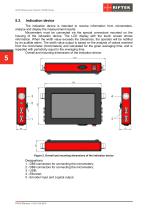
Width Measurement System. RF590 Series Indication device The indication device is intended to receive information from micrometers, analyze and display the measurement results. Micrometers must be connected via the special connectors mounted on the housing of the indication device. The LCD display with the touch screen shows information. When the width value exceeds the tolerances, the operator will be notified by an audible alarm. The width value output is based on the analysis of values received from the micrometer (micrometers) and calculated for the given averaging time, and is repeated with...
Open the catalog to page 5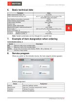
Width Measurement System. RF590 Series Basic technical data Parameter Width measurement range, mm Width measurement accuracy, µm Input interface (micrometers connection) Output interface (result transfer) Logical output (OK/NOK) Encoder input Software update, data transfer Measurement speed, measurements/second Power supply, V Power consumption, W Operating Ambient temperature, °С conditions Relative humidity, % Value by request up to +\-1 µm, depending on the accuracy of the micrometer used in the system RS485 Ethernet Open collector TTL USB up to 10000 220 V (±10 %) AC, with frequency of 50...
Open the catalog to page 6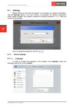
Width Measurement System. RF590 Series Before starting to work with the system, it is necessary to configure parameters. Tap the Settings button in the main window. The program will require a password. When initially installed, the program accepts the following password: 1111. Enter the password and tap Ok. Device settings Language In order to change the language of the program, tap Language, select the language support file, and tap Select.
Open the catalog to page 7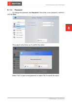
Width Measurement System. RF590 Series To change the password, tap Password. Then enter a new password, confirm it, and tap Save. The program will prompt you to confirm the action: Select "Yes" to save a new password, or select "No" to cancel the action.
Open the catalog to page 8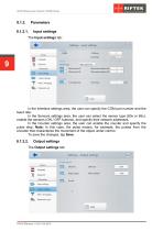
Width Measurement System. RF590 Series Input settings In the Interface settings area, the user can specify the COM port number and the baud rate. In the Sensors settings area, the user can select the sensor type (60x or 65x), enable the sensors (ON / OFF buttons), and specify their network addresses. In the Counter settings area, the user can enable the counter and specify the pulse step. Note: In this case, the pulse means, for example, the pulses from the encoder that characterize the movement of the object under control. To save the changes, tap Save. Output settings
Open the catalog to page 9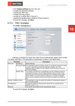
Width Measurement System. RF590 Series In the Output settings tab, the user can: · enable the Ethernet interface; · specify the UDP port; · enable the relay output; · enable an audible alarm ("Sound"); · specify the audible alarm duration ("Pulse duration"). To save the changes, tap Save. Filter / Averaging Filtering is intended to lower the noise of the measurement signal which results in a better resolution. The description of parameters is given in the table below. Parameter Description Filter type No filtering Without filtering. Moving Average The selectable number of filtration points for...
Open the catalog to page 10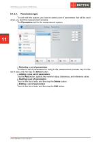
Width Measurement System. RF590 Series Parameters type To work with the system, you need to select a set of parameters that will be used when you start the measurement process. The Parameters tab for the measurement system: To select a set of parameters for using in the measurement process, tap it in the list of sets, and then tap the Select button. · Adding a new set of parameters Tap the Add button, specify the nominal value, tolerances, and reference value. · Deleting a set of parameters Tap it in the list of sets, and then tap the Delete button. · Editing a set of parameters Tap it in the...
Open the catalog to page 11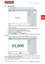
Width Measurement System. RF590 Series Measurement Tap the Measurement button in the main window. On the screen: This window displays: · name of the selected set of parameters (to the right of the window name); · current width value (big green (or red) digits); · values from the micrometers (Value D1 and Value D2); · nominal width value (Nominal); · tolerances (Tolerance '-' and Tolerance '+'). Tick the Save data box, if you want to save the measurement data to the database. To start the measurement process, tap the Start button. On the screen: If needed, you can tap the Stop button to stop the...
Open the catalog to page 12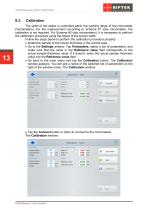
Width Measurement System. RF590 Series The width of the object is controlled within the working range of the micrometer (micrometers). For the measurement according to Scheme #1 (one micrometer), the calibration is not required. For Scheme #2 (two micrometers), it is necessary to perform the calibration procedure using the object of the known width. Follow the steps below to perform the calibration procedure properly: · Install the sample of the known thickness in the control area. · Go to the Settings window. Tap Parameters, select a set of parameters, and make sure that the value in the Reference...
Open the catalog to page 13All RIFTEK EUROPE catalogs and technical brochures
 PRODUCT CATALOG 2025
44 Pages
 RF603 Series Manual
49 Pages
 RF602 Series Manual
33 Pages
 RF603HS Series Manual
36 Pages
 RF609 (RF609Rt) Series Manual
33 Pages
 RF600 Series Manual
46 Pages
 RF605 Series Manual
29 Pages
 RF60i Series Manual
46 Pages
 RF62x Manual
174 Pages
 RF25x Series Manual
34 Pages
 RF651 Series Manual
32 Pages
 RF656 Series Manual
32 Pages
 RF656XY Series Manual
33 Pages
 Laser probes Manual
14 Pages
 Pipe ID Control System Manual
18 Pages
 Edge Sensor RF659 Series Manual
25 Pages
 RF627Smart-Weld manual
103 Pages
 PRODUCT CATALOG 2024
40 Pages


- Measuring device
- RIFTEK measuring system
- Windows software
- Industrial software
- Measurement software
- Position transducer
- Sorting machine
- Linear position transmitter
- Digital gauge
- Displacement transducer
- Linear displacement sensor
- Automatic sorting system
- RIFTEK automatic measuring system
- RIFTEK optical measuring system
- Inspection machine
- No-contact position sensor
- High-precision measurement system
- Linear encoder
- RIFTEK 3D scanner