
- Catalogs
- RIFTEK EUROPE
- Thickness Measurement System RF580 Manual


- Company
- Products
- Catalogs
- News & Trends
- Exhibitions
Thickness Measurement System RF580 Manual

Thickness Measurement System RF580 Manual
- Laser Sensors: RF603 Series for triangulation.
- Contact Encoders: RF25x Series for linear measurements.
- Indication Device: Displays sensor data and alerts for out-of-tolerance values.
- Analog Output Controller: RF002.1-485-8I for analog signal output.
Catalog excerpts

THICKNESS MEASUREMENT SYSTEM RF580 Series User's manual www.riftek.com [email protected]
Open the catalog to page 1
Thickness Measurement System. RF580 Series
Open the catalog to page 2
Thickness Measurement System. RF580 Series Safety precautions · · · · Use supply voltage and interfaces indicated in the system specifications. In connection/disconnection of cables, the system power must be switched off. Do not use the system in locations close to powerful light sources. To obtain stable results, wait about 20 minutes after sensor activation to achieve uniform sensor warm-up. · The indication device must be grounded and connected to the grounding bus by a separate branch. The system has been developed for use in industry and meets the requirements of the following Directives:...
Open the catalog to page 3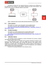
Thickness Measurement System. RF580 Series According to Scheme #2, the material thickness is defined as the difference in the distances to two surfaces of the material measured by each of the sensors. The position of the sensors is calibrated relative to each other. 4 Figure 1. Scheme #1 with one sensor (left) and Scheme #2 with two sensors (right) Laser sensors The system can contain Laser triangulation sensors RF603 Series. The User's manual for Laser triangulation sensors RF603 Series: https://riftek.com/media/documents/rf60x/rf603/Laser_Triangulation_Sensors_R F603_Series_eng.pdf Contact...
Open the catalog to page 4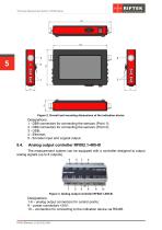
Thickness Measurement System. RF580 Series Figure 2. Overall and mounting dimensions of the indication device Designations: 1 - DB9 connectors for connecting the sensors (Point 1); 2 - DB9 connectors for connecting the sensors (Point 2); 3 - USB; 4 - Ethernet; 5 - Encoder input and Logical output. Analog output controller RF002.1-485-8I The measurement system can be equipped with a controller designed to output analog signals (up to 8 outputs). Figure 3. Analog output controller RF002.1-485-8I Designations: 1-8 – analog output connectors for control points; 9 – power connectors +24V; 10 – connectors...
Open the catalog to page 5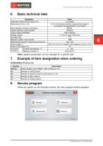
Thickness Measurement System. RF580 Series Basic technical data Parameter Thickness measurement range, mm Measurement error, mm Input interface, sensors connection Output interface, result transfer Logical output (OK/NOK) Analog outputs Encoder input Software update, data transfer Measurement speed, measurements/second Power supply, V Power consumption, W Operating Ambient temperature, °С conditions Relative humidity, % Value by request ±0.1% of the laser sensors measurement range or according to the specification for encoders RS485 Ethernet Open collector 4...20 mА, load <500 Ohm TTL USB up...
Open the catalog to page 6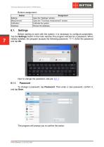
Thickness Measurement System. RF580 Series Buttons assignment: Button Settings Measurement Calibration Database Assignment Open the "Settings" window. Open the "Thickness measurement" window. Calibrate the system. Browse the database. Before starting to work with the system, it is necessary to configure parameters. Tap the Settings button in the main window.The program will ask for a password. When initially installed, the program accepts the following password: 1111. Enter the password and tap Ok. To change a password, tap Password. Then enter a new password, confirm it, and tap Save. The program...
Open the catalog to page 7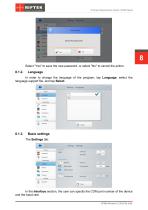
Thickness Measurement System. RF580 Series 8 Select "Yes" to save the new password, or select "No" to cancel the action. In order to change the language of the program, tap Language, select the language support file, and tap Select. Basic settings The Settings tab: In the Interface section, the user can specify the COM port number of the device and the baud rate. RF580 [Revision 2.0.0] 20.02.2020
Open the catalog to page 8
Thickness Measurement System. RF580 Series In the Output signals section, the user can: · enable the Ethernet interface and specify the UDP port; · enable relay outputs and specify the pulse duration; · enable the analog output. In the Counter section, the user can enable the counter and specify the pulse step. Note: In this case, the pulse means, for example, the pulses from the encoder that characterize the movement of the object under control. To save the changes, tap Save. In the Parameters tab, the user can set general parameters and filtering. The general parameters are described in the...
Open the catalog to page 9
Thickness Measurement System. RF580 Series Number of filtration points Description each measurement. Subsequently, the mean value will be output as the median. If the number of filter points is an even number, then the two average measurement values are added up and divided by two. This parameter specifies the number of measurement values to which the filter applies. To save the changes, tap Save. In this tab, the user can select the measurement mode, specify the number of sensors in the system and their network addresses. To select the measurement mode, use the Measurement mode drop-down list....
Open the catalog to page 10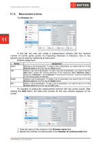
Thickness Measurement System. RF580 Series Measurement scheme The Scheme tab: 11 In this tab, the user can create a measurement scheme with the required number of control points (points for measuring thickness or distance). One or two sensors can be used for measuring at each point. Buttons assignment: Button Select Add Delete Edit Assignment Selecting a set of parameters. To select a set of parameters, you need to tap on it in the Scheme name list and then tap the Select button. Adding a new set of parameters. To add a new set of parameters, you need to tap the Add button, specify the nominal...
Open the catalog to page 11
Thickness Measurement System. RF580 Series 12 3. For each point, select the sensors from the drop-down list. 4. Specify the nominal thickness value (Nominal value), tolerances (Tolerance '-' and Tolerance '+') and the value of the boundaries of the analog outputs. 5. Perform the same actions for each measurement point. To change the current edited point, tap on the button with the corresponding name (Point 1, Point 2...). 6. Save the changes by tapping the Save button.
Open the catalog to page 12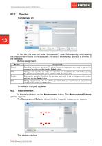
Thickness Measurement System. RF580 Series 13 In this tab, the user can enter the operator's data. Subsequently, when saving the measurement results to the database, the data of the selected operator is entered to the database. Buttons assignment: Button Select Assignment Selecting the current operator. To select the current operator, you need to tap on the personnel number and then tap the Select button. Adding a new operator. To add a new operator, you need to tap the Add button, specify the personnel number, last name and first name of the operator. Deleting the operator. To delete the operator,...
Open the catalog to page 13All RIFTEK EUROPE catalogs and technical brochures
 PRODUCT CATALOG 2025
44 Pages
 RF603 Series Manual
49 Pages
 RF602 Series Manual
33 Pages
 RF603HS Series Manual
36 Pages
 RF609 (RF609Rt) Series Manual
33 Pages
 RF600 Series Manual
46 Pages
 RF605 Series Manual
29 Pages
 RF60i Series Manual
46 Pages
 RF62x Manual
174 Pages
 RF25x Series Manual
34 Pages
 RF651 Series Manual
32 Pages
 RF656 Series Manual
32 Pages
 RF656XY Series Manual
33 Pages
 Laser probes Manual
14 Pages
 Pipe ID Control System Manual
18 Pages
 Edge Sensor RF659 Series Manual
25 Pages
 RF627Smart-Weld manual
103 Pages
 PRODUCT CATALOG 2024
40 Pages


- Measuring device
- RIFTEK measuring system
- Windows software
- Industrial software
- Measurement software
- Position transducer
- Sorting machine
- Linear position transmitter
- Digital gauge
- Displacement transducer
- Linear displacement sensor
- RIFTEK micrometer
- Automatic sorting system
- RIFTEK automatic measuring system
- Inspection machine
- RIFTEK optical measuring system
- No-contact position sensor
- Linear encoder
- RIFTEK 3D scanner
- High-precision measurement system