- Catalogs
- RIFTEK EUROPE
- Stepped Hole ID Measurement System Manual
- Company
- Products
- Catalogs
- News & Trends
- Exhibitions
Stepped Hole ID Measurement System Manual
1 /14Pages

Stepped Hole ID Measurement System Manual
1 /14Pages
Catalog excerpts

STEPPED HOLE ID MEASUREMENT SYSTEM RF096-15/40-50/70 Series User's manual www.riftek.com [email protected]
Open the catalog to page 1
Stepped Hole ID Measurement System. RF096-15/40-50/70 Series
Open the catalog to page 2
Stepped Hole ID Measurement System. RF096-15/40-50/70 Series Safety precautions · · · · Use supply voltage and interfaces indicated in the system specifications. In connection/disconnection of cables, the system power must be switched off. Do not use the system in locations close to powerful light sources. The system must be grounded. The system has been developed for use in industry and meets the requirements of the following Directives: · EU directive 2014/30/EU. Electromagnetic compatibility (EMC). · EU directive 2011/65/EU, “RoHS“ category 9. Laser safety The system makes use of a c.w. 660...
Open the catalog to page 3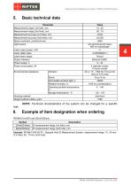
Stepped Hole ID Measurement System. RF096-15/40-50/70 Series Basic technical data Parameter Measurement range (1st hole), mm Measurement range (2nd hole), mm Measurement accuracy (1st hole), mm Measurement accuracy (2nd hole), mm Space resolution, points/turnover Light source Laser output power, mW Laser safety class Laser beam shape Output interface Power supply, V Power consumption, W Environmental resistance Vibration Shock Permissible ambient light, lx Relative humidity, % Operating ambient temperature, ° С Storage temperature, °С Housing material Weight (without cable), gram Value 15...40...
Open the catalog to page 4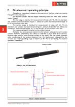
Stepped Hole ID Measurement System. RF096-15/40-50/70 Series Structure and operating principle Operation of the system is based on the scanning of the hole surface by rotating triangulation laser sensors. The system contains the two stages measuring head with three laser sensors inside, Figure 1. The first stage is intended for measurement of holes with 15...40 mm diameters and contains one laser sensor (Figure 1, sensor #1) with the measurement range of 6...21 mm from the head axis. The second stage is intended for measurement of holes with 50...70 mm diameters and contains two laser sensors...
Open the catalog to page 5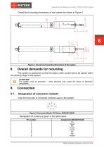
Stepped Hole ID Measurement System. RF096-15/40-50/70 Series Overall and mounting dimensions of the system are shown in Figure 2. Figure 2. Overall and mounting dimensions of the system Overall demands for mounting The system is positioned so that the object under control has to be placed within the working range of the system. ATTENTION! The system must be grounded – static electricity may cause the failure of electronic components. Connection Designation of connector contacts View from the side of connector contacts used in the system: Figure 3. Connector Binder 712 Series, #09-0427-80-08 Designation...
Open the catalog to page 6
Stepped Hole ID Measurement System. RF096-15/40-50/70 Series Cable Designation of cable wires is given in the table below: Pin number RJ-45 RJ-45 RJ-45 RJ-45 free lead free lead free lead free lead Assignment #09-0427-80-08 TX+ TXRX+ RXAL (output) Power+ IN (input) Power- Wire color White-orange Orange White-green Green White-blue Blue White-brown Brown Network setting All systems are shipped with the following default network configuration: IP address of the system – 192.168.0.3. Configure your PC's network card in the next address space: 192.168.0.Х. Connect system directly to PC or through...
Open the catalog to page 7
Stepped Hole ID Measurement System. RF096-15/40-50/70 Series The measurement process is fully automated and operation of the system is reduced to the work with the software. Service software General information The service software is intended for: · Testing and demonstration of the work of the system. · Setting parameters. · Calibration. The service software includes: · SDK library. · RF096 Test Program. System requirements · Operating system Windows 7 and later. · Microsoft Visual C++ Runtime Redistributable for Windows 64-bit. Shipped with the package (you need to run vcredist_x64.exe). Description...
Open the catalog to page 8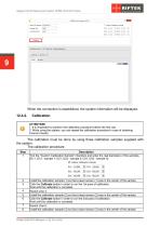
Stepped Hole ID Measurement System. RF096-15/40-50/70 Series When the connection is established, the system information will be displayed. Calibration ATTENTION! 1. It is imperative to perform the calibration procedure before the first use. 2. While using the system, you can repeat the calibration procedure in case of obtaining incorrect results. The calibration must be done by using three calibration samples supplied with the system. The calibration procedure: Step 1 Description Tick the "Custom Calibration Sample" checkbox and enter the real diameters of the samples (D11, D12 - sample 1; D21,...
Open the catalog to page 9
Stepped Hole ID Measurement System. RF096-15/40-50/70 Series Description Click the Calibrate button in order to run the 3rd pass of calibration. Wait until the calibration is complete. When you have calibrated the system, it's ready to run the measurement. Click the Measure button in order to start the measurement process. The program will display the calculated values. You may turn on and off a scale grid by clicking the Grid button. You may zoom and move the image when the Auto button is unpressed (shown in gray). To zoom the image, use the mouse wheel. To move the image, press the left mouse...
Open the catalog to page 10
Stepped Hole ID Measurement System. RF096-15/40-50/70 Series Beijing Haiwei Lutong Technology Co., Ltd Chongqing Wolf Industrial Technology Co., Ltd Yard 1, Tianxing Street, Fangshan District, Beijing, China Tel: +86 10 8366 1866 Fax: +86 10 8366 1866 [email protected] www.haiwlt.com Room 2307 / 2308, Light of City international business building, No. 19 Jiangnan Avenue, Nan'an District, Chongqing, China Tel: 023 62832618 Fax: 023 62832113 [email protected] www.wolf-hk.com Beijing Gemston Mechanical & Electrical Equipment Co., Ltd Xi'an Win-Success Automation Technology Co.,Ltd RAILWAY INSTRUMENTS...
Open the catalog to page 11
Stepped Hole ID Measurement System. RF096-15/40-50/70 Series ALTHEN GmbH Meß- und Sensortechnik OPTICAL MICROMETERS ONLY Sapelloh 172, 31606 Warmsen, Germany Tel: +49 5767 96020 Fax: +49 5767 93004 [email protected] www.finger-kg.de EXCLUSIVE REPRESENTATIVE FOR RAILWAY EQUIPMENT ul. Wielowiejska 53, 44-120 Pyskowice, Poland Tel: +48 32 230 45 70 Fax: + 48 32 233 21 34 [email protected] [email protected] www.ascorail.pl Influx Big Data Solutions Pvt Ltd Paragon Instrumentation Engineers Pvt. Ltd. PT. DHAYA BASWARA SANIYASA No:2, Krishvi, Ground Floor, Old Airport Road, Domlur, Bangalore - 560071,...
Open the catalog to page 12All RIFTEK EUROPE catalogs and technical brochures
 PRODUCT CATALOG 2025
44 Pages
 RF603 Series Manual
49 Pages
 RF602 Series Manual
33 Pages
 RF603HS Series Manual
36 Pages
 RF609 (RF609Rt) Series Manual
33 Pages
 RF600 Series Manual
46 Pages
 RF605 Series Manual
29 Pages
 RF60i Series Manual
46 Pages
 RF62x Manual
174 Pages
 RF25x Series Manual
34 Pages
 RF651 Series Manual
32 Pages
 RF656 Series Manual
32 Pages
 RF656XY Series Manual
33 Pages
 Laser probes Manual
14 Pages
 Pipe ID Control System Manual
18 Pages
 Edge Sensor RF659 Series Manual
25 Pages
 RF627Smart-Weld manual
103 Pages
 PRODUCT CATALOG 2024
40 Pages


- Measuring device
- RIFTEK measuring system
- Windows software
- Industrial software
- Measurement software
- Position transducer
- Sorting machine
- Linear position transmitter
- Digital gauge
- Displacement transducer
- Linear displacement sensor
- Automatic sorting system
- RIFTEK automatic measuring system
- RIFTEK optical measuring system
- No-contact position sensor
- Inspection machine
- High-precision measurement system
- Linear encoder
- RIFTEK 3D scanner