- Catalogs
- RIFTEK EUROPE
- Shafts Geometry Measurement Machine RF800 Series Manual
- Company
- Products
- Catalogs
- News & Trends
- Exhibitions
Shafts Geometry Measurement Machine RF800 Series Manual
1 /36Pages

Shafts Geometry Measurement Machine RF800 Series Manual
1 /36Pages
Catalog excerpts

SHAFTS GEOMETRY MEASUREMENT MACHINE RF800 Series User's manual www.riftek.com [email protected]
Open the catalog to page 1
Shafts Geometry Measurement Machine. RF800 Series
Open the catalog to page 2
Shafts Geometry Measurement Machine. RF800 Series Safety precautions · · · · · All specialists must study this User's Manual before operating the machine. Use supply voltage and interfaces indicated in the machine specifications. In connection/disconnection of cables, the power must be switched off. Do not use the machine in locations close to powerful light sources. To obtain stable results, wait about 20 minutes after powering the machine to achieve the uniform warm-up of the micrometer. · During the measurement procedure, the protective doors of the machine must be closed. The machine has...
Open the catalog to page 3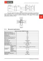
Shafts Geometry Measurement Machine. RF800 Series A two-axis optical micrometer contains two identical micrometers (in accordance with the scheme in Fig. 1) in one housing, placed at an angle of 90 degrees to each other, which makes it possible to control the diameter of the object in two mutually perpendicular directions, Fig. 2. Micrometer specifications Optical micrometer, RF656XY-35 model Measurement range, mm ±6х35 Minimum size of the object, mm 0.25 Maximum size of the object, mm 35 Accuracy, m ±1 Repeatability, m 0.5 Maximum scanning frequency, Hz Maximum update frequency, Hz Light source...
Open the catalog to page 4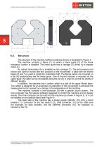
Shafts Geometry Measurement Machine. RF800 Series The structure of the machine (without protective doors) is illustrated in Figure 3. The machine contains a frame (1) on which a linear guide (2) of the linear translation system is installed. The linear guide has a carriage (3) driven by a stepper motor (4). An optical micrometer (5) is installed on the carriage (3). The end sensors (not shown) are used to monitor the end positions of the micrometer. A table with two Morse tapers (6 and 7) is used to install the controlled shaft. The Morse tapers are mounted on a bar (8) located along the the...
Open the catalog to page 5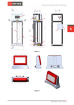
Shafts Geometry Measurement Machine. RF800 Series
Open the catalog to page 6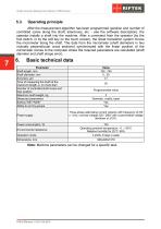
Shafts Geometry Measurement Machine. RF800 Series Operating principle After the measurement algorithm has been programmed (position and number of controlled zones along the shaft, tolerances, etc. - see the software description), the operator installs a shaft into the machine. After a command from the operator (by the foot switch, or by the soft key on the touch screen), the linear translation system moves the micrometer along the shaft. The data from the micrometer (shaft diameters in two mutually perpendicular cross sections) synchronized with the linear position of the micrometer comes to...
Open the catalog to page 7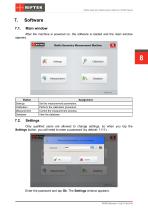
Shafts Geometry Measurement Machine. RF800 Series Software Main window After the machine is powered on, the software is loaded and the main window appears. Button Settings Calibration Measurement Database Assignment Set the measurement parameters. Perform the calibration procedure. Control the measurement process. View the database. Only qualified users are allowed to change settings, so when you tap the Settings button, you will need to enter a password (by default: 1111). Enter the password and tap Ok. The Settings window appears:
Open the catalog to page 8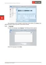
Shafts Geometry Measurement Machine. RF800 Series 9 The parameters menu is located in the left part of the window. The arrow in the upper left corner is used to go back to the previous window. Language To select the language, tap Language. The following window appears: Select the language and tap Save.
Open the catalog to page 9
Shafts Geometry Measurement Machine. RF800 Series Password To change the password, tap Password. The following window appears: Enter a new password and confirm it (the toggles in the fields are used to show/hide the entered characters). Tap Save. Parameters To change parameters, tap Parameters. The following window appears: Baud rate, bit/s Number of decimals Part type Calibration diameter D Note The COM port number of the internal RS485 network. This parameter can be changed only by the manufacturer. The baud rate of the COM port. This parameter can be changed only by the manufacturer. The displayed...
Open the catalog to page 10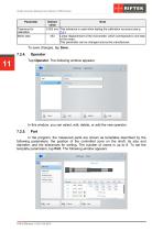
Shafts Geometry Measurement Machine. RF800 Series Parameter Tolerance for calibration Motor step Default Note value 0.002 mm This tolerance is used when testing the calibration accuracy (see p. 7.3.). 453 Linear displacement of the micrometer, which corresponds to one step of the motor. This parameter can be changed only by the manufacturer. To save changes, tap Save. Operator Tap Operator. The following window appears: In this window, you can select, edit, delete, or add the new operator. In the program, the measured parts are shown as templates described by the following parameters: the position...
Open the catalog to page 11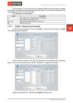
Shafts Geometry Measurement Machine. RF800 Series In this window, you can see a list of controlled shafts with their unique numbers and names. Parameters of the selected shaft are shown in the table (the selected shaft is highlighted in blue in the list to the left). The description of parameters: Name A L Gr0...Gr4 QC Description The position of the controlled zone on the shaft. The length of the controlled zone. Sorting groups (diameter value ± tolerance). Quality control sign. Adding / editing the part template To add the part template to the list, tap Add. To edit the part template, tap Edit....
Open the catalog to page 12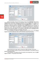
Shafts Geometry Measurement Machine. RF800 Series 13 Enter the diameter value and the tolerance value into the Diameter field and the Tolerance field respectively. Enter the parameters of the controlled zone, namely, the position of the zone on the shaft (Size A) and the zone length (Size L). In addition, it is necessary to enter the number of controlled sections (Sections d): 2 or 3. When "2" is selected, the measurements are performed in two sections spaced from the edges of the zone for 3 mm. When "3" is selected, an additional measurement is made in the center of the zone. The diameter of...
Open the catalog to page 13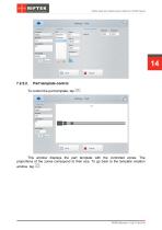
Shafts Geometry Measurement Machine. RF800 Series Part template control To control the part template, tap This window displays the part template with the controlled zones. The proportions of the zones correspond to their size. To go back to the template creation window, tap
Open the catalog to page 14All RIFTEK EUROPE catalogs and technical brochures
 PRODUCT CATALOG 2025
44 Pages
 RF603 Series Manual
49 Pages
 RF602 Series Manual
33 Pages
 RF603HS Series Manual
36 Pages
 RF609 (RF609Rt) Series Manual
33 Pages
 RF600 Series Manual
46 Pages
 RF605 Series Manual
29 Pages
 RF60i Series Manual
46 Pages
 RF62x Manual
174 Pages
 RF25x Series Manual
34 Pages
 RF651 Series Manual
32 Pages
 RF656 Series Manual
32 Pages
 RF656XY Series Manual
33 Pages
 Laser probes Manual
14 Pages
 Pipe ID Control System Manual
18 Pages
 Edge Sensor RF659 Series Manual
25 Pages
 RF627Smart-Weld manual
103 Pages
 PRODUCT CATALOG 2024
40 Pages


- Measuring device
- RIFTEK measuring system
- Windows software
- Industrial software
- Measurement software
- Position transducer
- Sorting machine
- Linear position transmitter
- Digital gauge
- Displacement transducer
- Linear displacement sensor
- Automatic sorting system
- RIFTEK automatic measuring system
- RIFTEK optical measuring system
- No-contact position sensor
- Inspection machine
- High-precision measurement system
- Linear encoder
- RIFTEK 3D scanner