- Catalogs
- RIFTEK EUROPE
- RF656XY Series Manual
- Company
- Products
- Catalogs
- News & Trends
- Exhibitions
RF656XY Series Manual
1 /33Pages

RF656XY Series Manual
1 /33Pages
Catalog excerpts

OPTICAL MICROMETER RF656XY Series User's manual www.riftek.com [email protected]
Open the catalog to page 1
Optical Micrometers. RF656XY Series
Open the catalog to page 2
Optical Micrometers. RF656XY Series
Open the catalog to page 3
Optical Micrometers. RF656XY Series Safety precautions · Use supply voltage and interfaces indicated in the sensor specifications. · In connection/disconnection of cables, the micrometer power must be switched off. · Do not use micrometers in locations close to powerful light sources. · To obtain stable results, wait about 20 minutes after micrometer activation to achieve uniform micrometer warm-up. The micrometers have been developed for use in industry and meet the requirements of the following Directives: · EU directive 2014/30/EU. Electromagnetic compatibility (EMC). · EU directive 2011/65/EU,...
Open the catalog to page 4
Optical Micrometers. RF656XY Series Basic technical data RF656XY Measurement range, mm Minimum size of the object1, mm Accuracy2, µm Repeatability3, µm Maximum scanning frequency, Hz Maximum update frequency, Hz Light source Lase safety class Output interface digital analog 2.4 – 5 V (CMOS, TTL) three outputs, NPN: 100 mA max; 40 V max 24 (9...36) from 1.5 to 2 IP64 20 g / 10…1000 Hz, 6 hours for each of XYZ axes 30 g / 6 ms -10…+60 Synchronization input Logic output Power supply, V Power consumption, W Enclosure rating Vibration Environmenta Shock l resistance Operation temperature, °С Relative...
Open the catalog to page 5
Optical Micrometers. RF656XY Series Modifications: Model SERIAL – 485, 485-ET ANALOG – no, I, U LOUT – no, LOUT IN – no, IN AL – no, AL CC – CC M – 0.1 m...10 m AK – no, AK SERIAL – 485, 485-ET ANALOG – no, I, U LOUT – no, LOUT IN – no, IN AL – no, AL CC – CC M – 0.1 m...10 m AK – no, AK SERIAL – 485, 485-ET ANALOG – no, I, U LOUT – no, LOUT IN – no, IN AL – no, AL CC – CC M – 0.1 m...10 m AK – no, AK SERIAL – 485, 485-ET ANALOG – no, I, U LOUT – no, LOUT IN – no, IN AL – no, AL CC – CC M – 0.1 m...10 m AK – no, AK SERIAL – 485, 485-ET ANALOG – no, I, U LOUT – no, LOUT IN – no, IN AL – no, AL...
Open the catalog to page 6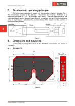
Optical Micrometers. RF656XY Series Structure and operating principle The micrometer operation is based on the so-called ‘shadow’ principle, Fig.1. The micrometer consists of two blocks – transmitter and receiver. Radiation of a semiconductor laser or LED 1 is collimated by a lens 2. With an object placed in the collimated beam region, shadow image formed is scanned with a CCD photo-detector array 3. A processor 4 calculates the position (size) of the object from the position of shadow border (borders). Overall and mounting dimensions of the RF656XY micrometers are shown in Figures 2-7.
Open the catalog to page 7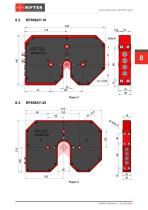
Optical Micrometers. RF656XY Series
Open the catalog to page 8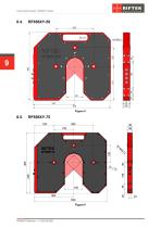
Optical Micrometers. RF656XY Series
Open the catalog to page 9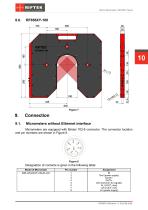
Optical Micrometers. RF656XY Series Connection Micrometers without Ethernet interface Micrometers are equipped with Binder 702-8 connector. The connector location and pin numbers are shown in Figure 8. Designation of contacts is given in the following table: Model of Micrometer Assignment IN Gnd (power supply) DATA+ DATAGnd (common for signals) AL (LOUT_max) U/I (LOUT_min) U+ (power supply)
Open the catalog to page 10
Optical Micrometers. RF656XY Series Micrometers with Ethernet interface Micrometers contain an additional Binder 712-4 connector. The connector location and pin numbers are shown in Figure 9. Designation of contacts is given in the table below: Model of Micrometer ЕТ Configuration parameters The nature of operation of the micrometer depends on its configuration parameters (operation modes), which can be changed only by transmission of commands through serial port RS485. The basic parameters are as follows: This parameter specifies one of the three result sampling options in the case where the...
Open the catalog to page 11
Optical Micrometers. RF656XY Series Note 1. It should be noted that the ‘sampling mode’ and ‘sampling period’ parameters control only the transmission of data. The micrometer operation algorithm is so built that measurements are taken at a maximum possible rate determined by the integration time period, the measurement results is sent to buffer and stored therein until a new result arrives. The above-mentioned parameters determine the method of the readout of the result form the buffer. Note 2. If the bit-serial interface is used to receive the result, the time required for data transmission...
Open the catalog to page 12
Optical Micrometers. RF656XY Series The border means “light-shadow’ transition or “shadow-light” transition which forms a shadow image of the object (see Figure 10). Measurement is only conducted in the case where the number of borders detected by micrometer corresponds to a given parameter. The polarity is the “light-shadow’ transition or “shadow-light” transition. Borders can be set with the same polarity and with the different polarity. Numbers of borders under control The measurement domain can include up to 64 borders, however, measurement can be made in relation to any two borders (hereinafter...
Open the catalog to page 13
Optical Micrometers. RF656XY Series This parameter defines the network address of the sensor equipped with RS485 interface. Note. Network data communications protocol assumes the presence of ‘master’ in the net, which can be a computer or other information-gathering device, and from 1 to 127 ‘slaves’ (RF65x Series sensors) which support the protocol. Each ‘slave’ is assigned a unique network identification code – a device address. The address is used to form requests or inquiries all over the net. Each slave receive inquiries containing its unique address as well as ‘0’ address which is broadcast-oriented...
Open the catalog to page 14
Optical Micrometers. RF656XY Series first, and then follows higher tetrad. When multi-byte values are transferred, the transmission begins with lower byte. The following is the format of two ‘message’ data bursts for transmission of byte: DAT(7:0) Byte 0 1 "Answer’’ is data burst that can be transmitted by ‘slave’ in the course of the session. All messages with a message burst contain 1 in the most significant digit. Data in a message are transferred in tetrads. When byte is transmitted, lower tetrad goes first, and then follows higher tetrad. When multi-byte values are transferred, the transmission...
Open the catalog to page 15All RIFTEK EUROPE catalogs and technical brochures
 PRODUCT CATALOG 2025
44 Pages
 RF603 Series Manual
49 Pages
 RF602 Series Manual
33 Pages
 RF603HS Series Manual
36 Pages
 RF609 (RF609Rt) Series Manual
33 Pages
 RF600 Series Manual
46 Pages
 RF605 Series Manual
29 Pages
 RF60i Series Manual
46 Pages
 RF62x Manual
174 Pages
 RF25x Series Manual
34 Pages
 RF651 Series Manual
32 Pages
 RF656 Series Manual
32 Pages
 Laser probes Manual
14 Pages
 Pipe ID Control System Manual
18 Pages
 Edge Sensor RF659 Series Manual
25 Pages
 RF627Smart-Weld manual
103 Pages
 PRODUCT CATALOG 2024
40 Pages


- Measuring device
- RIFTEK measuring system
- Windows software
- Industrial software
- Measurement software
- Position transducer
- Sorting machine
- Linear position transmitter
- Digital gauge
- Displacement transducer
- Linear displacement sensor
- Automatic sorting system
- RIFTEK automatic measuring system
- RIFTEK optical measuring system
- Inspection machine
- No-contact position sensor
- High-precision measurement system
- Linear encoder
- RIFTEK 3D scanner