- Catalogs
- RIFTEK EUROPE
- RF656 Series Manual
- Company
- Products
- Catalogs
- News & Trends
- Exhibitions
RF656 Series Manual
1 /32Pages

RF656 Series Manual
1 /32Pages
Catalog excerpts

OPTICAL MICROMETER RF656 Series User's manual www.riftek.com [email protected]
Open the catalog to page 1
Optical Micrometers. RF656 Series
Open the catalog to page 2
Optical Micrometers. RF656 Series
Open the catalog to page 3
Optical Micrometers. RF656 Series Safety precautions · Use supply voltage and interfaces indicated in the sensor specifications. · In connection/disconnection of cables, the micrometer power must be switched off. · Do not use micrometers in locations close to powerful light sources. · To obtain stable results, wait about 20 minutes after micrometer activation to achieve uniform micrometer warm-up. The micrometers have been developed for use in industry and meet the requirements of the following Directives: · EU directive 2014/30/EU. Electromagnetic compatibility (EMC). · EU directive 2011/65/EU,...
Open the catalog to page 4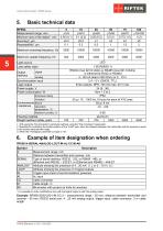
Optical Micrometers. RF656 Series Basic technical data RF656Measurement range, mm Minimum size of the object1, mm Accuracy2, µm Repeatability3, µm Maximum scanning frequency, Hz Maximum update frequency, Hz Light source Lase safety class Output interface 1 (IEC60825-1) RS232 (max 921.6 kbit/s) or RS485 (max 921.6 kbit/s) or Ethernet & (RS32 or RS485) digital analog 2.4 – 5 V (CMOS, TTL) three outputs, NPN: 100 mA max; 40 V max 24 (9...36) from 1.5 to 2 IP64 20 g / 10…1000 Hz, 6 hours for each of XYZ axes 30 g / 6 ms -10…+60 Synchronization input Logic output Power supply, V Power consumption,...
Open the catalog to page 5
Optical Micrometers. RF656 Series Parameters L – 36 mm SERIAL – 232, 485, 232-ET, 485-ET ANALOG – no, I, U LOUT – no, LOUT IN – no, IN AL – no, AL CC – CC M – 0.1 m...10 m AK – no, AK L – 56 mm...100 mm SERIAL – 232, 485, 232-ET, 485-ET ANALOG – no, I, U LOUT – no, LOUT IN – no, IN AL – no, AL CC – CC M – 0.1 m...10 m AK – no, AK L – 50 mm...100 mm (large base on request) SERIAL – 232, 485, 232-ET, 485-ET ANALOG – no, I, U LOUT – no, LOUT IN – no, IN AL – no, AL CC – CC M – 0.1 m...10 m AK – no, AK L – 50 mm...200 mm (large base on request) SERIAL – 232, 485, 232-ET, 485-ET ANALOG – no, I, U...
Open the catalog to page 6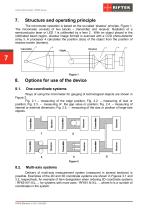
Optical Micrometers. RF656 Series Structure and operating principle The micrometer operation is based on the so-called ‘shadow’ principle, Figure 1. The micrometer consists of two blocks – transmitter and receiver. Radiation of a semiconductor laser or LED 1 is collimated by a lens 2. With an object placed in the collimated beam region, shadow image formed is scanned with a CCD photo-detector array 3. A processor 4 calculates the position (size) of the object from the position of shadow border (borders). One-coordinate systems Ways of using the micrometer for gauging of technological objects...
Open the catalog to page 7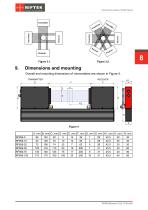
Optical Micrometers. RF656 Series Dimensions and mounting Overall and mounting dimensions of micrometers are shown in Figure 4.
Open the catalog to page 8
Optical Micrometers. RF656 Series Micrometers are equipped with cable connectors (CC option). Micrometers with the Ethernet interface contain two connectors. Micrometers without Ethernet interface Micrometers are equipped with Binder 702-8 connector. The connector location and pin numbers are shown in Figure 5. Designation of contacts is given in the table below: Model of Micrometer 232 - U/I(LOUT) - IN-AL - CC Assignment IN Gnd (power supply) TXD RXD Gnd (common for signals) AL (LOUT_max) U/I (LOUT_min) U+ (power supply) IN Gnd (power supply) DATA+ DATAGnd (common for signals) AL (LOUT_max)...
Open the catalog to page 9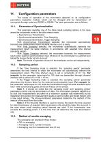
Optical Micrometers. RF656 Series Configuration parameters The nature of operation of the micrometer depends on its configuration parameters (operation modes), which can be changed only by transmission of commands through serial port RS232 or RS485. The basic parameters are as follows: This parameter specifies one of the three result sampling options in the case where the micrometer works in the data stream mode: · Asynchronous Transmission · Synchronous transmission, Time Sampling · Synchronous transmission, Trigger Sampling With Asynchronous Transmission selected, the micrometer automatically...
Open the catalog to page 10
Optical Micrometers. RF656 Series When averaging over a number of results is selected, sliding average is calculated. The use of averaging makes it possible to reduce the output noise and increase the micrometer resolution. Number of averaged values/time of averaging This parameter specifies the number of source results to be averaged for deriving the output value. Averaging over a number of results does not affect the data update in the micrometer output buffer. Note. The maximum value is 127. Measurement modes The micrometer can operate in the following modes: · Measurement of the position...
Open the catalog to page 11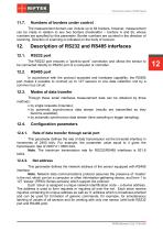
Optical Micrometers. RF656 Series Numbers of borders under control The measurement domain can include up to 64 borders, however, measurement can be made in relation to any two borders (hereinafter – borders А and В), whose numbers are specified by this parameter. Border numbers are counted in the direction of scanning. Direction of scanning is indicated on the body of receiver. The RS232 port ensures a “point-to-point” connection and allows the sensor to be connected directly to RS232 port of a computer or controller. In accordance with the protocol accepted and hardware capability, the RS485...
Open the catalog to page 12
Optical Micrometers. RF656 Series Factory parameters table Parameter Baud rate Net address Mode of data transfer Interfacing protocol Serial data transmission format Data message has the following format: The even parity bit pads 8-bit data to even parity. Communication sessions types The communications protocol is formed by communication sessions, which are only initiated by the ‘master’ (PC, controller). There are two kinds of sessions with such structures: 1) “request”, [“message”] — [“answer”], square brackets include optional elements 2) “request” — “data stream” — [“request”]. “Request”...
Open the catalog to page 13All RIFTEK EUROPE catalogs and technical brochures
 PRODUCT CATALOG 2025
44 Pages
 RF603 Series Manual
49 Pages
 RF602 Series Manual
33 Pages
 RF603HS Series Manual
36 Pages
 RF609 (RF609Rt) Series Manual
33 Pages
 RF600 Series Manual
46 Pages
 RF605 Series Manual
29 Pages
 RF60i Series Manual
46 Pages
 RF62x Manual
174 Pages
 RF25x Series Manual
34 Pages
 RF651 Series Manual
32 Pages
 RF656XY Series Manual
33 Pages
 Laser probes Manual
14 Pages
 Pipe ID Control System Manual
18 Pages
 Edge Sensor RF659 Series Manual
25 Pages
 RF627Smart-Weld manual
103 Pages
 PRODUCT CATALOG 2024
40 Pages


- Measuring device
- RIFTEK measuring system
- Windows software
- Industrial software
- Measurement software
- Position transducer
- Sorting machine
- Linear position transmitter
- Digital gauge
- Displacement transducer
- Linear displacement sensor
- Automatic sorting system
- RIFTEK automatic measuring system
- RIFTEK optical measuring system
- Inspection machine
- No-contact position sensor
- High-precision measurement system
- Linear encoder
- RIFTEK 3D scanner