- Catalogs
- RIFTEK EUROPE
- RF60i Series Manual
- Company
- Products
- Catalogs
- News & Trends
- Exhibitions
RF60i Series Manual
1 /46Pages

RF60i Series Manual
1 /46Pages
Catalog excerpts

LASER SENSORS FOR PAVEMENT PROFILE AND TEXTURE MEASUREMENT RF60i Series User's manual www.riftek.com [email protected]
Open the catalog to page 1
Laser Sensors For Pavement Profile And Texture Measurement. RF60i Series
Open the catalog to page 2
Laser Sensors For Pavement Profile And Texture Measurement. RF60i Series
Open the catalog to page 3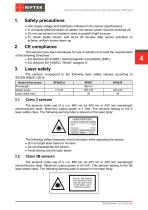
Laser Sensors For Pavement Profile And Texture Measurement. RF60i Series Safety precautions · · · · Use supply voltage and interfaces indicated in the sensor specifications. In connection/disconnection of cables, the sensor power must be switched off. Do not use sensors in locations close to powerful light sources. To obtain stable results, wait about 20 minutes after sensor activation to achieve uniform sensor warm-up. The sensors have been developed for use in industry and meet the requirements of the following Directives: · EU directive 2014/30/EU. Electromagnetic compatibility (EMC). · EU...
Open the catalog to page 4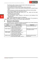
Laser Sensors For Pavement Profile And Texture Measurement. RF60i Series The following safety measures should be taken while operating the sensor: · Do not target laser beam to humans. · Avoid staring into the laser beam through optical instruments. · Mount the sensor so that the laser beam is positioned above or below the eyes level. · Mount the sensor so that the laser beam does not fall onto a mirror surface. · Use protective goggles while operating the sensor. · Avoid staring at the laser beam going out of the sensor and the beam reflected from a mirror surface. · Do not disassemble the sensor....
Open the catalog to page 5
Laser Sensors For Pavement Profile And Texture Measurement. RF60i Series Basic technical data Model Base distance X, mm Measurement range, mm Linearity, % of the range Resolution, % of the range Temperature drift Max. measurement frequency, Hz Light source Output power, mW Laser safety class (IEC/EN 60825-1:2014) Laser spot shape Laser spot size "beginningmiddle-end of the range", mm Output interface: Digital №1 Digital №2 Analog RS232 or RS485 (max. 921600 baud) Ethernet (max. 100 Mbit) 4…20 mA (load 500 Ohm) or 0…10 V Synchronization input, V Logic output Power supply, V Power consumption,...
Open the catalog to page 6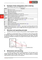
Laser Sensors For Pavement Profile And Texture Measurement. RF60i Series Example of item designation when ordering RF60i-X/D-SERIAL-ANALOG-IN-AL-СС(90X)(R)-M-H-P-B Base distance (beginning of the range), mm SERIAL ANALOG The type of serial interface: (232 (RS232) or 485 (RS485)) and (ET (Ethernet)) Attribute showing the presence of 4…20 mA ( I ) or 0…10 V ( U ) Sensor with trigger input (input of synchronization) User programmed input/output signal Cable gland - CG, or cable connector - CC (Binder 712, IP67) Note 1: sensors with the Ethernet interface have 2 connectors or two cable glands. Note...
Open the catalog to page 7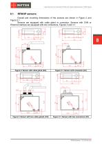
Laser Sensors For Pavement Profile And Texture Measurement. RF60i Series Overall and mounting dimensions of the sensors are shown in Figure 2 and Figure 2.1. Sensors are equipped with cable gland or connector. Sensors with CAN or Ethernet interface are equipped with two connectors, Figures 3 and 3.1. Figure 2. Sensor with cable gland (CG) Figure 2.1. Sensor with connector (CC) Figure 3. Sensor with two cable glands (CG) Figure 3.1. Sensor with two connectors (CC)
Open the catalog to page 8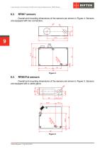
Laser Sensors For Pavement Profile And Texture Measurement. RF60i Series Overall and mounting dimensions of the sensors are shown in Figure 4. Sensors are equipped with two connectors. Overall and mounting dimensions of the sensors are shown in Figure 5. Sensors are equipped with a cable gland.
Open the catalog to page 9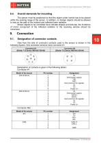
Laser Sensors For Pavement Profile And Texture Measurement. RF60i Series Overall demands for mounting The sensor must be positioned so that the object under control has to be placed within the working range of the sensor. In addition, no foreign objects should be allowed to stay on the path of the incident and reflected laser radiation. Where objects to be controlled have intricate shapes and textures, the incidence of mirror component of the reflected radiation to the receiving window should be minimized. Designation of connector contacts View from the side of connector contacts used in the...
Open the catalog to page 10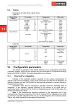
Laser Sensors For Pavement Profile And Texture Measurement. RF60i Series Cables Designation of cable wires is given below: Cable #1 Pin number free lead free lead DB9 DB9 free lead free lead free lead DB9 Wire color Power U+ Gnd (power supply) TXD RXD U/I IN AL Gnd (common for signals) Power U+ Gnd (power supply) DATA+ DATAU/I IN AL Gnd (common for signals) Red Brown Green Yellow Blue White Pink Gray Red Brown Green Yellow Blue White Pink Gray Wire color White-orange Orange White-green White-orange Orange Green Cable #2 Model of the sensor -ЕТ- free leads Configuration parameters The nature of...
Open the catalog to page 11
Laser Sensors For Pavement Profile And Texture Measurement. RF60i Series Note 2. Increasing of this parameter expands the possibility of control of lowreflecting (diffuse component) surfaces; at the same time this leads to reduction of measurement frequency and increases the effects of exterior light (background) on the measurement accuracy. Factory setting of the limiting time of integration is 3200 s. Note 3. Decreasing of this parameter lets to increase measurement frequency, but can decrease measurement accuracy. Sampling mode This parameter specifies one of the two result sampling options...
Open the catalog to page 12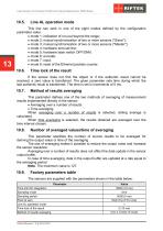
Laser Sensors For Pavement Profile And Texture Measurement. RF60i Series Line AL operation mode This line can work in one of the eight modes defined by the configuration parameter value: · mode 1: indication of run-out beyond the range; · mode 2: mutual synchronization of two or more sensors ("Slave"); · mode 3: mutual synchronization of two or more sensors ("Master"); · mode 4: hardware zero-set line; · mode 5: hardware laser switch OFF/ONN; · mode 6: encoder; · mode 7: input; · mode 8: reset of the Ethernet packets counter. Time lock of the result If the sensor does not find the object or if...
Open the catalog to page 13All RIFTEK EUROPE catalogs and technical brochures
 PRODUCT CATALOG 2025
44 Pages
 RF603 Series Manual
49 Pages
 RF602 Series Manual
33 Pages
 RF603HS Series Manual
36 Pages
 RF609 (RF609Rt) Series Manual
33 Pages
 RF600 Series Manual
46 Pages
 RF605 Series Manual
29 Pages
 RF62x Manual
174 Pages
 RF25x Series Manual
34 Pages
 RF651 Series Manual
32 Pages
 RF656 Series Manual
32 Pages
 RF656XY Series Manual
33 Pages
 Laser probes Manual
14 Pages
 Pipe ID Control System Manual
18 Pages
 Edge Sensor RF659 Series Manual
25 Pages
 RF627Smart-Weld manual
103 Pages
 PRODUCT CATALOG 2024
40 Pages


- Measuring device
- RIFTEK measuring system
- Windows software
- Industrial software
- Measurement software
- Position transducer
- Sorting machine
- Linear position transmitter
- Digital gauge
- Displacement transducer
- RIFTEK micrometer
- Linear displacement sensor
- Automatic sorting system
- RIFTEK automatic measuring system
- RIFTEK optical measuring system
- Inspection machine
- No-contact position sensor
- High-precision measurement system
- Linear encoder
- RIFTEK 3D scanner