
- Catalogs
- RIFTEK EUROPE
- RF609 (RF609Rt) Series Manual


- Company
- Products
- Catalogs
- News & Trends
- Exhibitions
RF609 (RF609Rt) Series Manual

RF609 (RF609Rt) Series Manual
- Sensor ON/OFF: Controlled by parameter code 00h, where 1 turns the laser ON and 0 turns it OFF.
- Analog Output: Controlled by parameter code 01h, where 1 turns the analog output ON and 0 turns it OFF.
- Control Byte: Parameter code 02h manages averaging, sampling, and analog output modes using a control byte with specific bit configurations.
- Network Address: Parameter code 03h allows setting network addresses from 1 to 127.
- Data Transfer Rate: Parameter code 04h specifies the rate in increments of 2400 baud.
Catalog excerpts

LASER PROBES RF609, RF609Rt Series User's manual www.riftek.com [email protected]
Open the catalog to page 1
Laser Probes. RF609, RF609Rt Series
Open the catalog to page 2
Laser Probes. RF609, RF609Rt Series
Open the catalog to page 3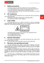
Laser Probes. RF609, RF609Rt Series Safety precautions · · · · Use supply voltage and interfaces indicated in the probe specifications. In connection/disconnection of cables, the probe power must be switched off. Do not use the probe in locations close to powerful light sources. To obtain stable results, wait about 20 minutes after powering on to achieve uniform probe warm-up. The probes have been developed for use in industry and meet the requirements of the following Directives: · EU directive 2014/30/EU. Electromagnetic compatibility (EMC). · EU directive 2011/65/EU, “RoHS“ category 9. Laser...
Open the catalog to page 4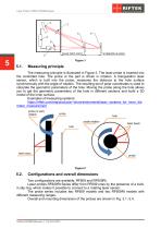
Laser Probes. RF609, RF609Rt Series Measuring principle The measuring principle is illustrated in Figure 2. The laser probe is inserted into the controlled hole. The probe or the part is driven in rotation. A triangulation laser sensor, which is built into the probe, measures the distance to the hole surface synchronously with the angle of rotation. The resulting set of polar coordinates is used to calculate the geometric parameters of the hole. Moving the probe along the hole allows you to get the geometric parameters of the hole in different sections and build a 3D model of the inner surface....
Open the catalog to page 5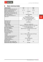
Laser Probes. RF609, RF609Rt Series Basic technical data RF609 (RF609Rt) Diameter of the laser sensor body, mm Range of controlled diameters, mm Depth of controlled holes, mm Base distance of the laser sensor, mm Working range of the laser sensor, mm Laser sensor linearity, % Max. measurement frequency, Hz Light source Output power, mW Laser safety class Output interface: Digital (RF609) Digital (RF609Rt) Analog (only for RF609Rt) Sync inputs (RF609), V Sync inputs (RF609Rt), V Power supply, V Power consumption, W Environmental resistance: Enclosure rating Vibration Shock Operating ambient temperature,...
Open the catalog to page 6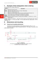
Laser Probes. RF609, RF609Rt Series Example of item designation when ordering Probe with a built-in slip ring. Blue laser option (405 nm or 450 nm). Only for 16/48 probes. Minimum controlled diameter, mm. Maximum controlled diameter (when the probe is located along the hole axis), mm. Probe length (prior consultation with the manufacturer is required). Type of serial interface for RF609Rt: 232 (RS232) or 485 (RS485). Attribute showing the presence of analog output for RF609Rt: 4…20 mA (I) or 0…10 V (U). Example. RF609Rt-9/19-100-232-I-3 – Probe with a built-in slip ring, red semiconductor laser,...
Open the catalog to page 7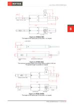
Laser Probes. RF609, RF609Rt Series 8 Figure 3.2. RF609-9/19Rt. The length of the optical part of the probe - on request. Figure 3.3. RF609-16/48. The minimum possible length of the probe (without cable) is 180 mm. The greater length is possible on request. Figure 3.4. RF609-16/48Rt. The length of the optical part of the probe - on request.
Open the catalog to page 8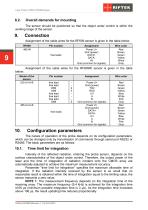
Laser Probes. RF609, RF609Rt Series Overall demands for mounting The sensor should be positioned so that the object under control is within the working range of the sensor. Connection Assignment of the cable wires for the RF609 sensor is given in the table below: RF609 485-IN Assignment Power U+ Gnd (power) DATA+ DATAIN Gnd (common for signals) free leads Wire color Red Brown Green Yellow White Gray Assignment of the cable wires for the RF609Rt sensor is given in the table below: Model of the sensor 232-U/I-A-B Pin number free lead free lead DB9 DB9 free lead free lead free lead DB9 Wire color...
Open the catalog to page 9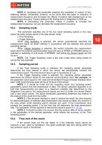
Laser Probes. RF609, RF609Rt Series NOTE 2. Increasing this parameter expands the possibility of control of lowreflecting (diffuse component) surfaces; at the same time this leads to reduction of measurement frequency and increases the effects of exterior light (background) on the measurement accuracy. Factory setting of the limiting time of integration is 3200 s. NOTE 3. Decreasing this parameter makes it possible to increase the measurement frequency, but can decrease the measurement accuracy. Sampling mode This parameter specifies one of the two result sampling options in the case where the...
Open the catalog to page 10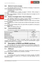
Laser Probes. RF609, RF609Rt Series Method of results averaging This parameter defines one of the two methods of averaging of measurement results implemented directly in the sensor: · Averaging over a number of results · Time averaging When averaging over a number of results is selected, sliding average is calculated. When time averaging is selected, the results obtained are averaged over the time interval chosen. Number of averaged values / time of averaging This parameter specifies the number of source results to be averaged for deriving the output value or time of averaging (discreteness -...
Open the catalog to page 11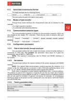
Laser Probes. RF609, RF609Rt Series Serial data transmission format The data message has the following format: 1 start-bit The even parity bit pads 8-bit data to even parity. Modes of data transfer Through these serial interfaces the measurement data can be obtained by two methods: · by single requests (inquiries); · by automatic data streaming (stream). Communication sessions types The communications protocol is formed by communication sessions, which are only initiated by the ‘master’ (PC, controller). There are two kinds of sessions with such structures: 1) “request”, [“message”] — [“answer”],...
Open the catalog to page 12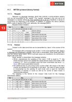
Laser Probes. RF609, RF609Rt Series RIFTEK protocol (binary format) 'Request' is a two-byte message, which fully controls a communication session and can be transmitted by the 'master'. The ‘request’ message is the only one of all messages in a session where the most significant bit is set at 0, therefore, it serves to synchronize the beginning of the session. In addition, it contains the device address (ADR), code of request (COD) and, optionally, the message [MSG]. Request format ('master'): lower tetrad of the 0th byte higher tetrad of the 0th byte lower tetrad of the 1st byte higher tetrad...
Open the catalog to page 13All RIFTEK EUROPE catalogs and technical brochures
 PRODUCT CATALOG 2025
44 Pages
 RF603 Series Manual
49 Pages
 RF602 Series Manual
33 Pages
 RF603HS Series Manual
36 Pages
 RF600 Series Manual
46 Pages
 RF605 Series Manual
29 Pages
 RF60i Series Manual
46 Pages
 RF62x Manual
174 Pages
 RF25x Series Manual
34 Pages
 RF651 Series Manual
32 Pages
 RF656 Series Manual
32 Pages
 RF656XY Series Manual
33 Pages
 Laser probes Manual
14 Pages
 Pipe ID Control System Manual
18 Pages
 Edge Sensor RF659 Series Manual
25 Pages
 RF627Smart-Weld manual
103 Pages
 PRODUCT CATALOG 2024
40 Pages


- Measuring device
- RIFTEK measuring system
- Windows software
- Industrial software
- Measurement software
- Position transducer
- Sorting machine
- Linear position transmitter
- Digital gauge
- Displacement transducer
- Linear displacement sensor
- RIFTEK micrometer
- Automatic sorting system
- RIFTEK automatic measuring system
- Inspection machine
- RIFTEK optical measuring system
- No-contact position sensor
- Linear encoder
- RIFTEK 3D scanner
- High-precision measurement system