- Catalogs
- RIFTEK EUROPE
- RF605 Series Manual
- Company
- Products
- Catalogs
- News & Trends
- Exhibitions
RF605 Series Manual
1 /29Pages

RF605 Series Manual
1 /29Pages
Catalog excerpts
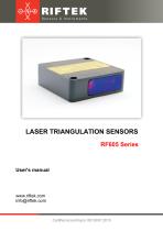
LASER TRIANGULATION SENSORS RF605 Series User's manual www.riftek.com [email protected]
Open the catalog to page 1
Laser Triangulation Sensors. RF605 Series valid for sensors with serial numbers 11000 and higher
Open the catalog to page 2
Laser Triangulation Sensors. RF605 Series valid for sensors with serial numbers 11000 and higher
Open the catalog to page 3
Laser Triangulation Sensors. RF605 Series Safety precautions · · · · Use supply voltage and interfaces indicated in the sensor specifications. In connection/disconnection of cables, the sensor power must be switched off. Do not use sensors in locations close to powerful light sources. To obtain stable results, wait about 20 minutes after sensor activation to achieve uniform sensor warm-up. The sensors have been developed for use in industry and meet the requirements of the following Directives: · EU directive 2014/30/EU. Electromagnetic compatibility (EMC). · EU directive 2011/65/EU, “RoHS“ category...
Open the catalog to page 4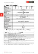
Laser Triangulation Sensors. RF605 Series Basic technical data RF605Base distance X, мм Measurement range, mm Linearity, % Resolution, % Temperature drift Max. sampling frequency, Hz Light source 45/100 65/250 45 65 100 250 ±0.1 of the range 0.02 of the range 0.02% of the range/°С 2000 red semiconductor laser, 660 nm wavelength Laser safety class Output interface Digital Analog Synchronization input Logic output Power supply, V Power consumption, W Environmental resistance Enclosure rating Vibration Shock Operating ambient temperature, °С Permissible ambient light, lx Relative humidity, % Storage...
Open the catalog to page 5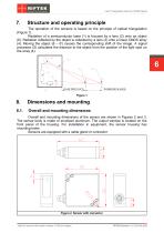
Laser Triangulation Sensors. RF605 Series Structure and operating principle The operation of the sensors is based on the principle of optical triangulation (Figure 1). Radiation of a semiconductor laser (1) is focused by a lens (2) onto an object (6). Radiation reflected by the object is collected by a lens (3) onto a linear CMOS array (4). Moving the object (6 – 6') causes the corresponding shift of the image. A signal processor (5) calculates the distance to the object from the position of the light spot on the array (4). Overall and mounting dimensions Overall and mounting dimensions of the...
Open the catalog to page 6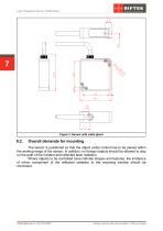
Laser Triangulation Sensors. RF605 Series Figure 3. Sensor with cable gland Overall demands for mounting The sensor is positioned so that the object under control has to be placed within the working range of the sensor. In addition, no foreign objects should be allowed to stay on the path of the incident and reflected laser radiation. Where objects to be controlled have intricate shapes and textures, the incidence of mirror component of the reflected radiation to the receiving window should be minimized. valid for sensors with serial numbers 11000 and higher
Open the catalog to page 7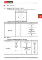
Laser Triangulation Sensors. RF605 Series Designation of connector contacts View from the side of connector contacts used in the sensor is shown below. Binder 702 Series, #09-0427-80-08 8 Designation of contacts is given in the following table: Model of the sensor 232-U/I-IN-AL Assignment IN Gnd (power supply) TXD RXD Gnd (common for signals) AL U/I Power supply U+ IN Gnd (power supply) DATA+ DATAGnd (common for signals) AL U/I Power supply U+ Cables Designation of cable wires is given in the table below: Pin number free lead free lead DB9 DB9 free lead free lead free lead DB9 valid for sensors...
Open the catalog to page 8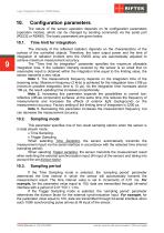
Laser Triangulation Sensors. RF605 Series Configuration parameters The nature of the sensor operation depends on its configuration parameters (operation modes), which can be changed by sending commands via the serial port (RS232 or RS485). The basic parameters are given below. Time limit for integration The intensity of the reflected radiation depends on the characteristics of the surface of the controlled objects. Therefore, the laser output power and the time of integration of radiation incident onto the CMOS array are automatically adjusted to achieve maximum measurement accuracy. The "Time...
Open the catalog to page 9
Laser Triangulation Sensors. RF605 Series Note 1. It should be noted that the ‘sampling mode’ and ‘sampling period’ parameters control only the transmission of data. The sensor operation algorithm is built in such a way that measurements are taken at the maximum possible rate determined by the integration time period, the measurement result is sent to the buffer and stored therein until a new result arrives. The above parameters determine how the result is read from the buffer. Note 2. If the bit-serial interface is used to receive the result, the time required to transfer data at the selected...
Open the catalog to page 10
Laser Triangulation Sensors. RF605 Series Mutual synchronization Hardware zero-set/ Hardware laser ON/OFF Time lock of the result If the sensor does not detect an object, or if the authentic result cannot be obtained, a zero value is transferred. This parameter sets the time during which the last authentic result is transferred instead of a zero value. Discreteness of the time setting is 5 ms. Method of results averaging This parameter defines one of two methods of averaging the measurement results implemented directly in the sensor: · Averaging over a number of results · Time averaging When...
Open the catalog to page 11
Laser Triangulation Sensors. RF605 Series Time lock of the result Method of results averaging Number of averaged values 5 ms Over the number of results 1 The parameters are stored in non-volatile memory of the sensor. Correct changing of the parameters is carried out using the parameterization program supplied with the sensor or the user program. The RS232 port provides a "point-to-point" connection and allows the sensor to be connected directly to RS232 port of a computer or controller. In accordance with the accepted network protocol and hardware capabilities, the RS485 port makes it possible...
Open the catalog to page 12
Laser Triangulation Sensors. RF605 Series Factory parameters Parameter Value 9600 bit/s 1 request Baud rate Network address Mode of data transfer Interfacing protocol Serial data transmission format The data message has the following format: The even parity bit pads 8-bit data to even parity. Communication session types The communication protocol is formed by communication sessions that are initiated only by the ‘master’ (PC, controller). There are two kinds of sessions with the following structures: 1) “request”, [“message”] — [“answer”], square brackets include optional elements. 2) “request”...
Open the catalog to page 13All RIFTEK EUROPE catalogs and technical brochures
 PRODUCT CATALOG 2025
44 Pages
 RF603 Series Manual
49 Pages
 RF602 Series Manual
33 Pages
 RF603HS Series Manual
36 Pages
 RF609 (RF609Rt) Series Manual
33 Pages
 RF600 Series Manual
46 Pages
 RF60i Series Manual
46 Pages
 RF62x Manual
174 Pages
 RF25x Series Manual
34 Pages
 RF651 Series Manual
32 Pages
 RF656 Series Manual
32 Pages
 RF656XY Series Manual
33 Pages
 Laser probes Manual
14 Pages
 Pipe ID Control System Manual
18 Pages
 Edge Sensor RF659 Series Manual
25 Pages
 RF627Smart-Weld manual
103 Pages
 PRODUCT CATALOG 2024
40 Pages


- Measuring device
- RIFTEK measuring system
- Windows software
- Industrial software
- Measurement software
- Position transducer
- Sorting machine
- Linear position transmitter
- Digital gauge
- Displacement transducer
- RIFTEK micrometer
- Linear displacement sensor
- Automatic sorting system
- RIFTEK automatic measuring system
- RIFTEK optical measuring system
- Inspection machine
- No-contact position sensor
- High-precision measurement system
- Linear encoder
- RIFTEK 3D scanner