- Catalogs
- RIFTEK EUROPE
- RF603HS Series Manual
- Company
- Products
- Catalogs
- News & Trends
- Exhibitions
RF603HS Series Manual
1 /36Pages

RF603HS Series Manual
1 /36Pages
Catalog excerpts

LASER TRIANGULATION SENSORS RF603HS Series User's manual www.riftek.com [email protected]
Open the catalog to page 1
Laser Triangulation Sensors. RF603HS Series valid for sensors with serial numbers 17559 and higher
Open the catalog to page 2
Laser Triangulation Sensors. RF603HS Series valid for sensors with serial numbers 17559 and higher
Open the catalog to page 3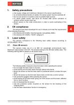
Laser Triangulation Sensors. RF603HS Series Safety precautions · · · · Use supply voltage and interfaces indicated in the sensor specifications. In connection/disconnection of cables, the sensor power must be switched off. Do not use sensors in locations close to powerful light sources. To obtain stable results, wait about 20 minutes after sensor activation to achieve uniform sensor warm-up. · Mount sensor on the metal construction in order to avoid overheating of the sensor. The sensors have been developed for use in industry and meet the requirements of the following Directives: · EU directive...
Open the catalog to page 4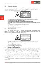
Laser Triangulation Sensors. RF603HS Series The sensors make use of a cw 660 nm wavelength semiconductor laser. Maximum output power is 5 mW. The sensors belong to the 3R laser safety class. The following warning label is placed on the sensor body: The following safety measures should be taken while operating the sensor: · Do not target the laser beam to humans. · Avoid staring into the laser beam through optical instruments. · Mount the sensor so that the laser beam is positioned above or below the eyes level. · Use protective goggles when operating the sensor. · Avoid staring into the laser...
Open the catalog to page 5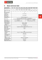
Laser Triangulation Sensors. RF603HS Series Basic technical data Temperature drift Light source red semiconductor laser (660 nm wavelength) or UV semiconductor laser (450 nm or 405 nm wavelength, BLUE version) Output power Laser safety class Output interface: Parameterization Data transfer Synchronization input Logic output Power supply Power consumption Environmental resistance: Enclosure rating Vibration IP67 20 g / 10…1000 Hz, 6 hours for each of XYZ axes Operating ambient temperature Permissible ambient light Relative humidity Storage temperature Housing material Weight (without cable) valid...
Open the catalog to page 6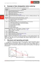
Laser Triangulation Sensors. RF603HS Series Example of item designation when ordering RF603HS(BLUE).F-X/D(R)-SERIAL-ANALOG-IN-AL-СС(R)(90)-M-H-P-B Symbol (BLUE) F X D (R) SERIAL Description UV semiconductor laser (450 nm or 405 nm). Maximal sampling frequency. Base distance (beginning of the range), mm. Measurement range, mm. Round shape laser spot (see p. 18.3.). The type of serial interface: (RS232 and Ethernet) – 232-ET or (RS485 and Ethernet) – 485ET. Attribute showing an analog output presence 0…10 V (U). User programmed signal, which has several purposes: 1) Trigger input (input of synchronization)....
Open the catalog to page 7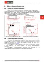
Laser Triangulation Sensors. RF603HS Series Overall and mounting dimensions Overall and mounting dimensions of the sensors are shown in Figure 2 and 2.1. Sensor package is made of anodized aluminum. The front panel of the package has two glass windows: one is output, the other for receiving radiation reflected from the object under control. The package also contains mounting holes. Sensors are equipped with cable glands or connectors. Figure 2. Sensor with cable glands (CG) Figure 2.1. Sensor with connectors (CC) Overall demands for mounting The sensor must be positioned so that the object under...
Open the catalog to page 8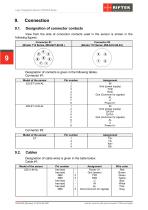
Laser Triangulation Sensors. RF603HS Series Designation of connector contacts View from the side of connector contacts used in the sensor is shown in the following figures. Connector #1 (Binder 712 Series, #09-0427-80-08 ) Connector #2 (Binder 712 Series, #09-0412-80-04 ) 9 Designation of contacts is given in the following tables. Connector #1: Model of the sensor 232-ET-U-IN-AL Assignment IN Gnd (power supply) TXD RXD Gnd (Common for signals) AL U Power U+ IN Gnd (power supply) DATA+ DATAGnd (Common for signals) AL U Power U+ Connector #2: Model of the sensor ЕТ Cables Designation of cable wires...
Open the catalog to page 9
Laser Triangulation Sensors. RF603HS Series Assignment Power U+ Gnd (power) DATA+ DATAU IN AL Gnd (Common for signals) free leads Wire color Red Brown Green Yellow Blue White Pink Gray Cable #2: Model of the sensor ЕТ Wire color White-orange Orange White-green Configuration parameters The nature of operation of the sensor depends on its configuration parameters (operation modes), which can be changed only by transmission of commands through serial port RS232 or RS485. The basic parameters are given below. "Time limit for integration" parameter Intensity of the reflected radiation depends on the...
Open the catalog to page 10
Laser Triangulation Sensors. RF603HS Series When the Time Sampling mode is selected, the sensor fills a buffer of transmitting (automatically transmits measurement results from the buffer of measurements into the buffer of transmitting) in accordance with the selected time interval (sampling period). When the Trigger Sampling mode is selected, the sensor fills a buffer of transmitting (automatically transmits measurement results from the buffer of measurements into the buffer of transmitting) when an external synchronization input (IN input of the sensor) is switched taking into account the division...
Open the catalog to page 11
Laser Triangulation Sensors. RF603HS Series In the "Indication of run-out beyond the range" mode, logical “1” occurs on the AL line if an object under control is located within the working range of the sensor, and logical "0" occurs if the object is absent in the working range. For example, in such mode this line can be used for controlling an actuator (a relay), which is activated when the object is present (absent) within the selected range (Fig. 3.1). The "Mutual synchronization” mode makes it possible to synchronize measurement times of two and more sensors. It is convenient to use this mode...
Open the catalog to page 12
Laser Triangulation Sensors. RF603HS Series Time lock of the result If the sensor does not detect an object, or if the authentic result cannot be obtained, a zero value is transferred. This parameter sets the time during which the last authentic result is transferred instead of a zero value. Discreteness of the time setting is 5 ms. Method of results averaging This parameter defines one of the two methods of averaging the measurement results implemented directly in the sensor: · Averaging over a number of results · Time averaging When averaging over a number of results is selected, sliding average...
Open the catalog to page 13All RIFTEK EUROPE catalogs and technical brochures
 PRODUCT CATALOG 2025
44 Pages
 RF603 Series Manual
49 Pages
 RF602 Series Manual
33 Pages
 RF609 (RF609Rt) Series Manual
33 Pages
 RF600 Series Manual
46 Pages
 RF605 Series Manual
29 Pages
 RF60i Series Manual
46 Pages
 RF62x Manual
174 Pages
 RF25x Series Manual
34 Pages
 RF651 Series Manual
32 Pages
 RF656 Series Manual
32 Pages
 RF656XY Series Manual
33 Pages
 Laser probes Manual
14 Pages
 Pipe ID Control System Manual
18 Pages
 Edge Sensor RF659 Series Manual
25 Pages
 RF627Smart-Weld manual
103 Pages
 PRODUCT CATALOG 2024
40 Pages


- Measuring device
- RIFTEK measuring system
- Windows software
- Industrial software
- Measurement software
- Position transducer
- Sorting machine
- Linear position transmitter
- Digital gauge
- Displacement transducer
- RIFTEK micrometer
- Linear displacement sensor
- Automatic sorting system
- RIFTEK automatic measuring system
- RIFTEK optical measuring system
- Inspection machine
- No-contact position sensor
- High-precision measurement system
- Linear encoder
- RIFTEK 3D scanner