- Catalogs
- RIFTEK EUROPE
- RF603 Series Manual
- Company
- Products
- Catalogs
- News & Trends
- Exhibitions
RF603 Series Manual
1 /49Pages

RF603 Series Manual
1 /49Pages
Catalog excerpts
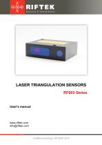
LASER TRIANGULATION SENSORS RF603 Series User's manual www.riftek.com [email protected]
Open the catalog to page 1
Laser Triangulation Sensors. RF603 Series Valid for sensors with serial numbers 19300 and higher
Open the catalog to page 2
Laser Triangulation Sensors. RF603 Series Valid for sensors with serial numbers 19300 and highe
Open the catalog to page 3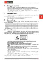
Laser Triangulation Sensors. RF603 Series Safety precautions · · · · Use supply voltage and interfaces indicated in the sensor specifications. In connection/disconnection of cables, the sensor power must be switched off. Do not use sensors in locations close to powerful light sources. To obtain stable results, wait about 20 minutes after sensor activation to achieve uniform sensor warm-up. The sensors have been developed for use in industry and meet the requirements of the following Directives: · EU directive 2014/30/EU. Electromagnetic compatibility (EMC). · EU directive 2011/65/EU, “RoHS“ category...
Open the catalog to page 4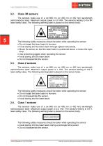
Laser Triangulation Sensors. RF603 Series The sensors make use of a cw 660 nm (or 405 nm or 450 nm) wavelength semiconductor laser. Maximum output power is 4.8 mW. The sensors belong to the 3R laser safety class. The following warning label is placed on the sensor body: The following safety measures should be taken while operating the sensor: · Do not target the laser beam to humans. · Avoid staring into the laser beam through optical instruments. · Mount the sensor so that the laser beam is positioned above or below the eyes level. · Use protective goggles when operating the sensor. · Avoid...
Open the catalog to page 5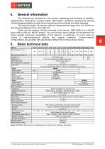
Laser Triangulation Sensors. RF603 Series General information The sensors are intended for non-contact measuring and checking of position, displacement, dimensions, surface profile, deformation, vibrations, sorting and sensing of technological objects as well as for measuring levels of liquid and bulk materials. The series includes 26 sensors with the measurement range from 2 to 1250 mm and the base distance from 10 to 260 mm. There are two options of laser mounted in the sensor: RED (660 nm) or BLUE laser (405 or 450 nm, BLUE version). The use of blue lasers instead of conventional red lasers...
Open the catalog to page 6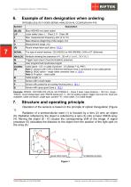
Laser Triangulation Sensors. RF603 Series Example of item designation when ordering RF603(BLUE)(L/Р).F-X/D(R)-SERIAL-ANALOG-IN-AL-СС(90X)(R)-M-H-P-B Blue (405/450 nm) laser option Laser safety class: L - Class 2, P - Class 3B Base distance (beginning of the range), mm Round shape laser spot (see p. 18.3.) The type of serial interface: 232 (RS232) or 485 (RS485); CAN or ET (Ethernet) Attribute showing the presence of 4…20 mA ( I ) or 0…10 V ( U ) Trigger input (input of synchronization) presence User programmed input/output signal Cable gland - CG, or cable connector - CC (Binder 712, IP67) Note...
Open the catalog to page 7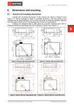
Laser Triangulation Sensors. RF603 Series Overall and mounting dimensions Overall and mounting dimensions of the sensors are shown in Figure 2 and Figure 2.1. Sensor package is made of anodized aluminum. The front panel of the package has two glass windows: one is output, the other for receiving radiation reflected from the object under control. The package also contains mounting holes. Sensors are equipped with a cable gland or connector. Sensors with CAN or Ethernet interface are equipped with two connectors, Figure 3 and Figure 3.1. Figure 2. Sensor with cable gland (CG) Figure 2.1. Sensor...
Open the catalog to page 8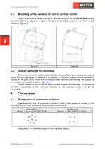
Laser Triangulation Sensors. RF603 Series Mounting of the sensors for mirror surface control Figure 4 shows the requirements for the mounting of the RF603-R-39/4 sensor for control of mirror objects and glass. The special mounting device is included into the shipping, Figure 5. Overall demands for mounting The sensor must be positioned so that the object under control has to be placed within the working range of the sensor. In addition, no foreign objects should be allowed to stay on the path of the incident and reflected laser radiation. Necessary free space for the sensor mounting is shown...
Open the catalog to page 9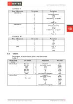
Laser Triangulation Sensors. RF603 Series Connector #1 Model of the sensor 232-U/I-IN-AL Assignment IN Gnd (power supply) TXD RXD Gnd (common for signals) AL U/I Power U+ IN Gnd (power supply) DATA+ DATAGnd (common for signals) AL U/I Power U+ Assignment TX+ TXRX+ RXCAN_H CAN_L Connector №2 Model of the sensor -ЕТ- Cables Designation of cable wires is given in the table below: Cable #1 Pin number free lead free lead DB9 DB9 free lead free lead free lead DB9 Valid for sensors with serial numbers 19300 and higher Wire color Power U+ Gnd (power supply) TXD RXD U/I IN AL Gnd (common for signals)...
Open the catalog to page 10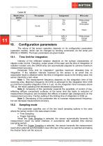
Laser Triangulation Sensors. RF603 Series Cable #2 Model of the sensor -ЕТ- free leads Wire color White-orange Orange White-green White-orange Orange Green Configuration parameters The nature of the sensor operation depends on its configuration parameters (operation modes), which can be changed by sending commands via the serial port (RS232 or RS485). The basic parameters are given below. Time limit for integration Intensity of the reflected radiation depends on the surface characteristic of objects under control. Therefore, output power of the laser and the time of integration of radiation incident...
Open the catalog to page 11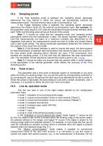
Laser Triangulation Sensors. RF603 Series Sampling period If the Time Sampling mode is selected, the ‘sampling period’ parameter determines the time interval in which the sensor will automatically transmit the measurement result. The time interval value is set in increments of 1 s. If the Trigger Sampling mode is selected, the ‘sampling period’ parameter determines the division factor for the external synchronization input. For example, for the parameter value equal to 100, data are transmitted through bit-serial interface when each 100th synchronizing pulse arrives at IN input of the sensor....
Open the catalog to page 12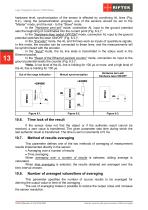
Laser Triangulation Sensors. RF603 Series hardware level, synchronization of the sensor is effected by combining AL lines (Fig. 6.2.). Using the parametrization program, one of the sensors should be set to the "Master" mode, and the rest - to the "Slave" mode. In the "Hardware zero-set" mode, connection AL input to the ground potential sets the beginning of coordinates into the current point (Fig. 6.3.)*. In the "Hardware laser switch OFF/ON" mode, connection AL input to the ground potential switches the laser ON/OFF (Fig. 6.3.)*. In the "Encoder" mode, the AL and IN lines work as inputs of quadrature...
Open the catalog to page 13All RIFTEK EUROPE catalogs and technical brochures
 PRODUCT CATALOG 2025
44 Pages
 RF602 Series Manual
33 Pages
 RF603HS Series Manual
36 Pages
 RF609 (RF609Rt) Series Manual
33 Pages
 RF600 Series Manual
46 Pages
 RF605 Series Manual
29 Pages
 RF60i Series Manual
46 Pages
 RF62x Manual
174 Pages
 RF25x Series Manual
34 Pages
 RF651 Series Manual
32 Pages
 RF656 Series Manual
32 Pages
 RF656XY Series Manual
33 Pages
 Laser probes Manual
14 Pages
 Pipe ID Control System Manual
18 Pages
 Edge Sensor RF659 Series Manual
25 Pages
 RF627Smart-Weld manual
103 Pages
 PRODUCT CATALOG 2024
40 Pages


- Measuring device
- RIFTEK measuring system
- Windows software
- Industrial software
- Measurement software
- Position transducer
- Sorting machine
- Linear position transmitter
- Digital gauge
- Displacement transducer
- Linear displacement sensor
- Automatic sorting system
- RIFTEK micrometer
- RIFTEK automatic measuring system
- RIFTEK optical measuring system
- No-contact position sensor
- Inspection machine
- High-precision measurement system
- Linear encoder
- RIFTEK 3D scanner