
- Catalogs
- RIFTEK EUROPE
- RF25x Series Manual


- Company
- Products
- Catalogs
- News & Trends
- Exhibitions
RF25x Series Manual

RF25x Series Manual
Catalog excerpts

ABSOLUTE LINEAR ENCODERS RF25x Series User's manual
Open the catalog to page 1
Absolute linear encoders, RF25X
Open the catalog to page 2
Absolute linear encoders, RF25X
Open the catalog to page 3
Absolute linear encoders, RF25X 1. Safety precautions Use supply voltage and interfaces indicated in the sensor specifications. In connection/disconnection of cables, the sensor power must be switched off. To obtain stable results, wait about 20 minutes after sensor activation to achieve uniform sensor warm-up. Electromagnetic compatibility The sensors have been developed for use in industry and meet the requirements of the following standards: EN 55022:2006 Information Technology Equipment. Radio disturbance characteristics. Limits and methods of measurement. EN 61000-6-2:2005 Electromagnetic...
Open the catalog to page 4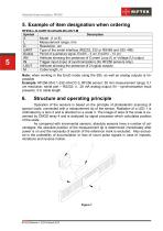
Absolute linear encoders, RF25X 5. Example of item designation when ordering RF25Х-L-D-UART-EncDxAN-IN-LOUT-М Symbol Х L D UART EncDx AN IN LOUT М Model (1 or 6) Measurement range, mm Resolution, um Type of the serial interface (RS232, 232 or RS485 and SSI, 485) Period of quadrature signal, EncD5 – 5 um, EncD10 – 10 um Attribute showing the presence of Current Loop (I) or Voltage (U) output Trigger input (input of synchronization) (for RF256 sensors only) Attribute showing the presence of 2 logical outputs Cable length, m Note: when working in the EncD mode using the SSI, as well as analog outputs...
Open the catalog to page 5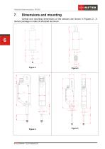
Absolute linear encoders, RF25X Overall and mounting dimensions of the sensors are shown in Figures 2…5. Sensor package is made of anodized aluminum.
Open the catalog to page 6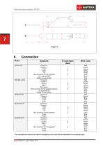
Absolute linear encoders, RF25X Connection Symbols Power U+ Power UTXD RXD IN Gnd (Common for the sygnals) U/I (UpLimitOC) AGND (LowLimitOC) Power U+ Power UDATA+ DATAIN (Clock+) Gnd (Common for the sygnals) (Clock-) U/I (UpLimitOC) AGND (LowLimitOC) Power U+ Power UEncB EncA Gnd Power U+ Power UTXD RXD IN Gnd (Common for the sygnals) EncB EncA Power U+ Power UDATA+ DATAIN Gnd (Common for the sygnals) EncB EncA Wire color Red Brown Green Yellow White Grey Blue Pink Red Brown Green Yellow White Grey Blue Pink Red Brown Blue Pink Grey Red Brown Green Yellow White Grey Blue Pink Red Brown Green...
Open the catalog to page 7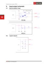
Absolute linear encoders, RF25X Input-output schematic Synchronization input Logical outputs
Open the catalog to page 8
Absolute linear encoders, RF25X 10. Operation modes and configuration parameters 10.1. Operation modes. Measurement data from sensors can be obtained through serial interface and/or on the analog output. Through the serial interface measurement data can be obtained by two methods: by single requests (inquiries); by automatic data streaming. Changing of the signal at analog output occurs in synchronism with the changing of the result transferred through the bit-serial interface. When RS485 or CAN or Ethernet interfaces are used, several sensors can be connected to the data collection device...
Open the catalog to page 9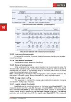
Absolute linear encoders, RF25X Data stream transfer with time synchronization Data stream transfer with external synchronization 10.2.3. Line correction parameter is intended for correction of encoder linearity (parameter changing can decrease encoder accuracy). 10.2.4. Zero position parameter is intended for assign of sensor's Zero Point 10.2.5. Range of analog output While working with the analog output, resolution can be increased by using the ‘Window in the operating range’ function which makes it possible to select a window of required size and position in the operating range of the sensor...
Open the catalog to page 10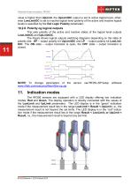
Absolute linear encoders, RF25X value is higher than UpLimit, the UpLimitOC output is set to active logical level, otherwise LowLimitOC is set to inactive logical level (polarity of the active and inactive logical levels is specified by the Out Logic Polarity parameter). 10.2.8. Polarity og logical outputs This sets polarity of the active and inactive states of the logical level outputs LowLimitOC and UpLimitOC. The Figure shows logical outputs switching diagrams depending on the state of polarity bits: HP – output polarity bit UpLimitOC and LP – output polarity bit LowLimitOC. The ON state –...
Open the catalog to page 11
Absolute linear encoders, RF25X 12. Description of Serial interfaces 12.1. RS232 port. The RS232 port ensures a “point-to-point” connection and allows the sensor to be connected directly to RS232 port of a computer or controller. In accordance with the protocol accepted and hardware capability, the RS485 port makes it possible to connect up to 127 sensors to one data collection unit by a common bus circuit. 12.3. Configuration parameters 12.3.1. Rate of data transfer through serial port. This parameter defines the rate of data transmission via the bit-serial interface in increments of 2400 bit/s....
Open the catalog to page 12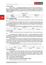
Absolute linear encoders, RF25X Inquiry” (INC) — is a two-byte message, which fully controls communication session. The ‘inquiry’ message is the only one of all messages in a session where most significant bit is set at 0, therefore, it serves to synchronize the beginning of the session. In addition, it contains the device address (ADR), code of inquiry (COD) and, optional, the message [MSG]. "Inquiry" format: "Message’’ is data burst that can be transmitted by ‘master’ in the course of the session. All messages with a "message" burst contain 1 in the most significant digit. Data in a message...
Open the catalog to page 13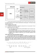
Absolute linear encoders, RF25X In this mode, the sensor synchronization input is used as Clock signal input, and the RS485 interface lines are used for transmission of Data signal. The level of Clock and Data signals is 5V. Enabling of the SSI mode is effected by setting SSI bit in the parameter "Check byte of sampling mode" (See Table 13.2). When the SSI mode is enabled: if no clock pulses are present at the synchronization input, the sensor operates in the RS485 mode; if a clock signal is present, the sensor switches to the SSI mode. In this case, the sensor does not respond to requests...
Open the catalog to page 14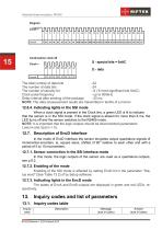
Absolute linear encoders, RF25X 15 The total number of data bits -32 The number of data bits -24 The number of security bit - 8 ( 8 most significant bits 0xAC) Clock pulse frequency - up to 500kHz Delay interval after sending of the package - 25 ms NOTE: The data (measurement result) are transmitted in tenths of a micron 12.6.4. Indicating lights in the SSI mode When a clock signal is present in the Clock line, a green LED is lit to indicate that the sensor is in the SSI mode. If the clock signal is absent for more than 8 ms, the LED turns off and the sensor switches to the RS485 mode. NOTE:...
Open the catalog to page 15All RIFTEK EUROPE catalogs and technical brochures
 PRODUCT CATALOG 2025
44 Pages
 RF603 Series Manual
49 Pages
 RF602 Series Manual
33 Pages
 RF603HS Series Manual
36 Pages
 RF609 (RF609Rt) Series Manual
33 Pages
 RF600 Series Manual
46 Pages
 RF605 Series Manual
29 Pages
 RF60i Series Manual
46 Pages
 RF62x Manual
174 Pages
 RF651 Series Manual
32 Pages
 RF656 Series Manual
32 Pages
 RF656XY Series Manual
33 Pages
 Laser probes Manual
14 Pages
 Pipe ID Control System Manual
18 Pages
 Edge Sensor RF659 Series Manual
25 Pages
 RF627Smart-Weld manual
103 Pages
 PRODUCT CATALOG 2024
40 Pages


- Measuring device
- RIFTEK measuring system
- Windows software
- Industrial software
- Measurement software
- Position transducer
- Sorting machine
- Linear position transmitter
- Digital gauge
- Displacement transducer
- Linear displacement sensor
- RIFTEK micrometer
- Automatic sorting system
- RIFTEK automatic measuring system
- Inspection machine
- RIFTEK optical measuring system
- No-contact position sensor
- RIFTEK 3D scanner
- High-precision measurement system