- Catalogs
- RIFTEK EUROPE
- Real time wheel geometry measurement system 3DWheel Manual
- Company
- Products
- Catalogs
- News & Trends
- Exhibitions
Real time wheel geometry measurement system 3DWheel Manual
1 /81Pages

Real time wheel geometry measurement system 3DWheel Manual
1 /81Pages
Catalog excerpts

REAL TIME WHEELS GEOMETRY MEASUREMENT SYSTEM 3DWheel Series User's manual www.riftek.com [email protected]
Open the catalog to page 1
Real Time Wheels Geometry Measurement System. 3DWheel Series
Open the catalog to page 2
Real Time Wheels Geometry Measurement System. 3DWheel Series
Open the catalog to page 3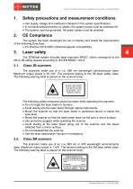
Real Time Wheels Geometry Measurement System. 3DWheel Series Safety precautions and measurement conditions · Use supply voltage and interfaces indicated in the system specifications. · In connection/disconnection of cables, the system power must be switched off. · The system must be grounded. All power cables must be shielded. The system has been developed for use in industry and meets the requirements of the following Directives: · EU directive 2014/30/EU (Electromagnetic compatibility). Laser safety The 3DWheel system includes laser scanners RF627, which correspond to the 2M or 3B safety classes...
Open the catalog to page 4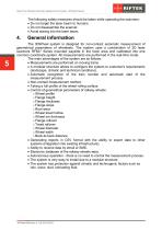
Real Time Wheels Geometry Measurement System. 3DWheel Series The following safety measures should be taken while operating the scanners: · Do not target the laser beam to humans. · Do not disassemble the scanner. · Avoid staring into the laser beam. General information The 3DWheel system is designed for non-contact automatic measurement of geometrical parameters of wheelsets. The system uses a combination of 2D laser scanners RF627 Series mounted wayside in the track area and calibrated into one common coordinate system. All measurements are performed in the real-time mode. The main advantages...
Open the catalog to page 5
Real Time Wheels Geometry Measurement System. 3DWheel Series Basic technical data Measurement range Parameter Flange height, mm Flange thickness, mm Flange slope, mm Rim thickness, mm Tire width, mm Wheel diameter, mm Back-to-back distance, mm Value 20...45 20...50 1...15 30...100 20...120 400...1400 according to the track width Measurement error Flange height, mm Flange thickness, mm Flange slope / qR factor, mm Rim thickness, mm Wheel width / Rim width, mm Wheel diameter, mm Back-to-back distance, mm Other technical data Parameter Power supply (control cabinet), V Power supply (air conditioning...
Open the catalog to page 6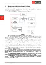
Real Time Wheels Geometry Measurement System. 3DWheel Series Structure and operating principle The 3DWheel system has a modular and open configuration, which makes it possible to adapt it to any types of railroad tracks and railway wheels, and to reduce the technical maintenance to a minimum. A functional diagram of the system is shown in Figure 1. The main modules of the 3DWheel system are as follows: 1) Laser scanning modules. These modules are intended for scanning of the wheelset. They contain 2D laser scanners RF627 Series mounted wayside in the track area and calibrated into one common...
Open the catalog to page 7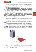
Real Time Wheels Geometry Measurement System. 3DWheel Series The 3DWheel system also includes a controller of RF700 series (see Annex 1). It controls the air conditioning cabinet, the power of the laser scanning modules and HTC boards in scanners, as well as the power of the moving blinds. It processes signals from four inductive sensors and generates sync pulses for scanners. The 3DWheel system operates as follows. The Position monitoring module detects the rolling stock. When the rolling stock is detected, the Control module turns on the Laser scanning modules and opens the protective blinds....
Open the catalog to page 8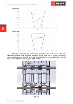
Real Time Wheels Geometry Measurement System. 3DWheel Series Inner side: Modules containing two scanners are placed on the outer side of the rail. Modules containing three scanners are placed on the inner side of the rail. In order to avoid mutual influence on each other, scanners located on the opposite sides of the rail have lasers of different wavelengths (RED and IR).
Open the catalog to page 9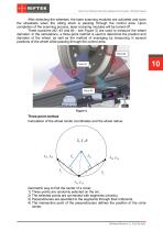
Real Time Wheels Geometry Measurement System. 3DWheel Series After detecting the wheelset, the laser scanning modules are activated and scan the wheelsets when the rolling stock is passing through the control area. Upon completion of the scanning process, laser scanning modules will be turned off. Three scanners (#2, #3 and #4 - see Figure 3) are used to measure the wheel diameter. In the calculations, a three-point method is used to determine the position and diameter of the wheel, as well as the method of averaging by measuring in several positions of the wheel while passing through the control...
Open the catalog to page 10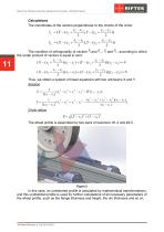
Real Time Wheels Geometry Measurement System. 3DWheel Series Calculations The coordinates of the vectors perpendicular to the chords of the circle: The condition of orthogonality of vectors the scalar product of vectors is equal to zero: 11 Thus, we obtain a system of linear equations with two unknowns X and Y. Solution Circle radius The wheel profile is assembled by two pairs of scanners: #1-2 and #4-5. In this case, an undistorted profile is calculated by mathematical transformations, and this undistorted profile is used for further calculations of all necessary parameters of the wheel profile,...
Open the catalog to page 11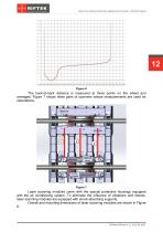
Real Time Wheels Geometry Measurement System. 3DWheel Series The back-to-back distance is measured at three points on the wheel and averaged. Figure 7 shows three pairs of scanners whose measurements are used for calculations. Laser scanning modules come with the special protective housings equipped with the air conditioning system. To eliminate the influence of vibrations and shocks, laser scanning modules are equipped with shock-absorbing supports. Overall and mounting dimensions of laser scanning modules are shown in Figure 8.
Open the catalog to page 12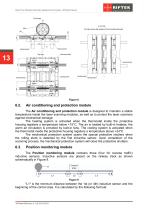
Real Time Wheels Geometry Measurement System. 3DWheel Series Air conditioning and protection module The Air conditioning and protection module is designed to maintain a stable temperature inside the laser scanning modules, as well as to protect the laser scanners against mechanical damage. The heating system is activated when the thermostat inside the protective housing registers a temperature below +15°С. The air is heated by built-in heaters, the warm air circulation is provided by built-in fans. The cooling system is activated when the thermostat inside the protective housing registers a temperature...
Open the catalog to page 13All RIFTEK EUROPE catalogs and technical brochures
 PRODUCT CATALOG 2025
44 Pages
 RF603 Series Manual
49 Pages
 RF602 Series Manual
33 Pages
 RF603HS Series Manual
36 Pages
 RF609 (RF609Rt) Series Manual
33 Pages
 RF600 Series Manual
46 Pages
 RF605 Series Manual
29 Pages
 RF60i Series Manual
46 Pages
 RF62x Manual
174 Pages
 RF25x Series Manual
34 Pages
 RF651 Series Manual
32 Pages
 RF656 Series Manual
32 Pages
 RF656XY Series Manual
33 Pages
 Laser probes Manual
14 Pages
 Pipe ID Control System Manual
18 Pages
 Edge Sensor RF659 Series Manual
25 Pages
 RF627Smart-Weld manual
103 Pages
 PRODUCT CATALOG 2024
40 Pages


- Measuring device
- RIFTEK measuring system
- Windows software
- Industrial software
- Measurement software
- Position transducer
- Sorting machine
- Linear position transmitter
- Digital gauge
- Displacement transducer
- RIFTEK micrometer
- Linear displacement sensor
- Automatic sorting system
- RIFTEK automatic measuring system
- RIFTEK optical measuring system
- Inspection machine
- No-contact position sensor
- High-precision measurement system
- Linear encoder
- RIFTEK 3D scanner