- Catalogs
- RIFTEK EUROPE
- Railway Wheel Profile Gauge IKP-5 Series (Model 2017) Manual
- Company
- Products
- Catalogs
- News & Trends
- Exhibitions
Railway Wheel Profile Gauge IKP-5 Series (Model 2017) Manual
1 /104Pages

Railway Wheel Profile Gauge IKP-5 Series (Model 2017) Manual
1 /104Pages
Catalog excerpts

LASER WHEEL PROFILOMETER IKP-5 Series, Model 2017 Year User's manual [email protected] www.riftek.com
Open the catalog to page 1
Laser Wheel Profilometer. IKP-5 Series, Model 2017 Year IKP-5 Series, Model 2017 Year [Revision 1.1.0] 10.11.2017
Open the catalog to page 2
Laser Wheel Profilometer. IKP-5 Series, Model 2017 Year
Open the catalog to page 3
Laser Wheel Profilometer. IKP-5 Series, Model 2017 Year IKP-5 Series, Model 2017 Year [Revision 1.1.0] 10.11.2017
Open the catalog to page 4
Laser Wheel Profilometer. IKP-5 Series, Model 2017 Year Safety precautions and measurement conditions · Prior to mounting the profilometer onto the wheel, areas of contact of the side supports with the wheel surface should be thoroughly cleaned from dirt. · When mounting the module on the wheel, do not allow heavy shocks of its support against the wheel. · The output window of the profilometer and profilometer supports must be carefully inspected and cleaned. · Do not use laser module in locations close to powerful light sources. The profilometers have been developed for use in industry and meet...
Open the catalog to page 5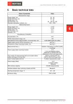
Laser Wheel Profilometer. IKP-5 Series, Model 2017 Year Basic technical data Name of parameter Measurement range Flange height, mm Flange thickness, mm Flange slope, mm Rim thickness, mm Diameter (calculation method), mm Measurement error Flange height, mm Flange thickness, mm Flange slope, mm Rim thickness, mm Diameter, mm Discreteness of indication All parameters, mm Profile measurement range, mm Discreteness of the profile formation, not worse than, mm Digital readout device (PDA) dimensions, mm Dimensions of laser scanning module, mm Measurement time, s Power supply (laser scanning module)...
Open the catalog to page 6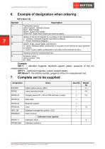
Laser Wheel Profilometer. IKP-5 Series, Model 2017 Year Example of designation when ordering IKP-V-М-S-T-R Profilometer version: without symbol - Standard version Short - Short handle SShort - Super short handle SShort-EB - Super short handle and external battery Options of the set of magnets for mounting on the internal/external rim face: S – standard. Standard magnets (specified by default). F – forced. Reinforced magnets. Options of the support plates embodiment: D – direct. Standard plates, profilometer is mounted on the internal rim face (specified by default). I – invert. Custom plates,...
Open the catalog to page 7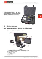
Laser Wheel Profilometer. IKP-5 Series, Model 2017 Year The profilometer comes in the special case that protects the device against any possible damage during transportation. Device structure Basic components of the device and their functions Fig. 1 shows basic components of the device: (1) Digital readout device (personal digital assistant, PDA) (2) Laser scanning module (3) Calibration block (4) Charging device (5) Data cable IKP-5 Series, Model 2017 Year [Revision 1.1.0] 10.11.2017
Open the catalog to page 8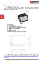
Laser Wheel Profilometer. IKP-5 Series, Model 2017 Year Digital readout device Digital readout device (PDA) is designed for control of the laser scanning module, data reception from the scanning module, indication of measurement results, parameter input, and data storage. Fig. 2 indicates: (1) Turn-on button (2) Charging indication, red/blue LED (3) Connector to PC USB-port or charging device (4) Flash memory card connector (5) Stylus (6) Bluetooth antenna Overall dimensions of PDA are shown in Figure 3: NOTE. Instead of a PDA, it is possible to use an Android gadget. In this case, the Android...
Open the catalog to page 9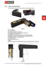
Laser Wheel Profilometer. IKP-5 Series, Model 2017 Year Laser scanning module The module is intended for laser scanning of the wheel surface. Fig. 4 indicates: (1) Turn ON button (2) Indicator of turn ON (red LED) (3) Indicator of Bluetooth connection (blue LED) (4) Charging device connector (5) Support for mounting of the device on the wheel flange (6) Magnetic support for mounting on the wheel side surface (7) Charging indication, red/green LED (8) Output window (9) Rim measurement rod · IKP-T Overall dimensions of the standard scanning module are shown in Figure 5. IKP-5 Series, Model 2017...
Open the catalog to page 10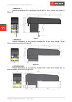
Laser Wheel Profilometer. IKP-5 Series, Model 2017 Year Overall dimensions of the scanning module with a short handle are shown in Figure 6. Overall dimensions of the scanning module with a very short handle (Super Short version) are shown in Figure 6.1. Overall dimensions of the scanning module with a very short handle and an external battery are shown in Figure 6.2. IKP-5 Series, Model 2017 Year [Revision 1.1.0] 10.11.2017
Open the catalog to page 11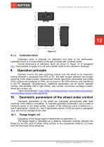
Laser Wheel Profilometer. IKP-5 Series, Model 2017 Year Calibration block Calibration block is intended for calibration and tests of the profilometer. Calibration block is a metal imitator of the part of wheel with a definite profile. Overall dimensions of calibration block are shown in Figure 1A of paragraph 30.3. Also possible is supply of a unit with a profile made to the customer’s drawings. Operation principle Operator mounts the laser scanning module onto the wheel to be measured. Having received a command from PDA or PC, the laser module performs non-contact scanning of the wheel surface....
Open the catalog to page 12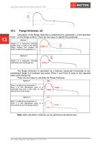
Laser Wheel Profilometer. IKP-5 Series, Model 2017 Year Calculation of the flange thickness is determined by parameter L3 that specifies Point 1 on the flange surface. There are two ways to specify the parameter: Method 1 Height L3 is measured vertically upward from a point of the wheel rolling surface, the position of which is defined by parameter L2. Method 2 Height L3 is measured vertically downward from the flange top. The flange thickness is calculated as a distance measured horizontally at any preselected height (L3) between two points (Point 1 and Point 2) lying on the opposite sides of...
Open the catalog to page 13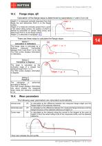
Laser Wheel Profilometer. IKP-5 Series, Model 2017 Year Flange slope, qR Calculation of the flange slope is determined by parameters L1 and L3 (or L4). Height L1 is measured vertically downward from the flange top and determines Point 3 on the flange surface. Height L4 is measured vertically upward from a point of the wheel rolling surface, the position of which is defined by parameter L2 (wheel rolling circle), and determines Point 4 on the flange surface. Height L3 is described in paragraph 10.2. There are three ways to calculate the flange slope: Method 1 Calculation in millimeters The flange...
Open the catalog to page 14All RIFTEK EUROPE catalogs and technical brochures
 PRODUCT CATALOG 2025
44 Pages
 RF603 Series Manual
49 Pages
 RF602 Series Manual
33 Pages
 RF603HS Series Manual
36 Pages
 RF609 (RF609Rt) Series Manual
33 Pages
 RF600 Series Manual
46 Pages
 RF605 Series Manual
29 Pages
 RF60i Series Manual
46 Pages
 RF62x Manual
174 Pages
 RF25x Series Manual
34 Pages
 RF651 Series Manual
32 Pages
 RF656 Series Manual
32 Pages
 RF656XY Series Manual
33 Pages
 Laser probes Manual
14 Pages
 Pipe ID Control System Manual
18 Pages
 Edge Sensor RF659 Series Manual
25 Pages
 RF627Smart-Weld manual
103 Pages
 PRODUCT CATALOG 2024
40 Pages


- Measuring device
- RIFTEK measuring system
- Windows software
- Industrial software
- Measurement software
- Position transducer
- Sorting machine
- Linear position transmitter
- Digital gauge
- Displacement transducer
- RIFTEK micrometer
- Linear displacement sensor
- Automatic sorting system
- RIFTEK automatic measuring system
- RIFTEK optical measuring system
- Inspection machine
- No-contact position sensor
- High-precision measurement system
- Linear encoder
- RIFTEK 3D scanner