
- Catalogs
- RIFTEK EUROPE
- Railway Wheel Profile Gauge IKP-5 Series (Model 2016) Manual


- Company
- Products
- Catalogs
- News & Trends
- Exhibitions
Railway Wheel Profile Gauge IKP-5 Series (Model 2016) Manual

Railway Wheel Profile Gauge IKP-5 Series (Model 2016) Manual
- Displayed Parameters: To enable display mode, press the "Show param." button. Double-click in the "Show/Hide" column to select or deselect parameters, then press "Save."
- L Parameters: Access by pressing the "L Parameters" button. Edit values by double-clicking in the "Value" column and entering new data. Save changes by pressing "Save."
- Preset Parameter Values: The document lists default values for L-parameters used in various calculations, such as flange slope, wheel diameter, and wear.
- Database Management: Create and manage database files for storing measurement results. Files are named by default with the format "wp_yy_mm_dd.ikp."
- Reference Profile Selection: Compare scanned wheel profiles with reference profiles stored in the PDA database. Users can request additional profiles from RIFTEK if needed.
- Measurement Scheme: Define sequences for measuring wheels. Users can select, view, or delete schemes, and create new ones using the PDA or a PC program.
- Tolerances Setting: Set and manage tolerance groups for geometric parameters. Critical values are highlighted in red, and near-critical values in orange.
- Wheel Type Selection: Assign specific measurement schemes, reference profiles, and parameters to different wheel types.
- Types of Measurements: Rapid measurements without saving results and detailed measurements with database maintenance.
- Measurement Process: Follow the program's prompts to measure wheels. Results beyond tolerances are highlighted. Users can view profiles and save satisfactory results.
- Wear and Defect Measurement: Special procedures for measuring even/uneven wear and defects like slides and cavities.
- Install the RF505Calibr program on a PC.
- Establish a Bluetooth connection between the scanning module and PC.
- Place the profilometer on the calibration unit and run the RF505Calibr program.
- Select the required port for Bluetooth connection to identify the device and read calibration parameters.
- Automatic testing involves specifying the number of measurements (5-10) and ensuring deviations from reference values do not exceed 0.1 mm.
- If deviations exceed permissible values, calibration is necessary.
- Select a reference profile, perform measurement, and execute auto-calibration.
- Save parameters if results are positive; otherwise, restore factory settings and recalibrate.
- Laser Wheel Profilometer (IKP Series): Measures wheel flange height, thickness, slope, and performs full profile scanning without wheel set roll-out.
- Portable Laser Rail Profilometer (PRP Series): Provides cross-section profile information and visualizes railhead profiles.
- Wheel Diameter Measuring Gauge (IDK Series): Measures wheel rolling circle diameter directly on rolling stock.
- Back-to-Back Distance Measuring Gauge (IMR Series): Measures back-to-back distance of wheels contactlessly.
- Disc Brakes Profile Gauge (IKD Series): Measures disc brakes profile parameters and visualizes profiles.
- Automatic Real-Time System: Measures geometrical parameters of railway wheels using 2D laser scanners.
Catalog excerpts

LASER WHEEL PROFILOMETER IKP-5 Series, Model 2016 Year User's manual [email protected] www.riftek.com
Open the catalog to page 1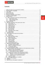
Laser Wheel Profilometer. IKP-5 Series, Model 2016 Year IKP-5 Series, Model 2016 Year [Revision 3.0.0] 04.01.2016
Open the catalog to page 2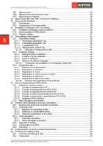
Laser Wheel Profilometer. IKP-5 Series, Model 2016 Year
Open the catalog to page 3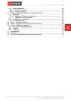
Laser Wheel Profilometer. IKP-5 Series, Model 2016 Year IKP-5 Series, Model 2016 Year [Revision 3.0.0] 04.01.2016
Open the catalog to page 4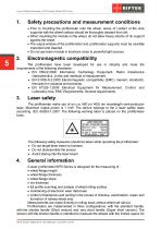
Laser Wheel Profilometer. IKP-5 Series, Model 2016 Year Safety precautions and measurement conditions · Prior to mounting the profilometer onto the wheel, areas of contact of the side supports with the wheel surface should be thoroughly cleaned from dirt. · When mounting the module on the wheel, do not allow heavy shocks of its support against the wheel. · The output window of the profilometer and profilometer supports must be carefully inspected and cleaned. · Do not use laser module in locations close to powerful light sources. Electromagnetic compatibility The profilometer have been developed...
Open the catalog to page 5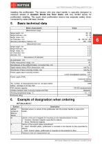
Laser Wheel Profilometer. IKP-5 Series, Model 2016 Year installing the profilometer. The version with very short handle is specially designed to measure wheels of Ansaldo Breda low floor trams with very limited space for profilometer installing. This super short profilometer version has separate battery block, connected by cable with laser module. Basic technical data Name of parameter Measurement range flange height, mm flange thickness, mm flange slope, mm rim thickness, mm diameter (calculation method), mm Measurement error flange height, mm flange thickness, mm flange slope, mm rim thickness,...
Open the catalog to page 6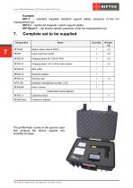
Laser Wheel Profilometer. IKP-5 Series, Model 2016 Year Example: IKP-Т – standard magnets; standard support plates; presence of the rim measurement rod. IKP-F-I – reinforced magnets; custom support plates. IKP-Short-T – the shorten handle; presence of the rim measurement rod. Digital readout device (PDA) Laser scanning module Charging device 9V 3.0A for laser module Data cable Bluetooth adapter Packing case Database management system (CD) User's manual Ca libra tion tools (option): RF505.11 Calibration block Calibration software The profilometer comes in the special case that protects the device...
Open the catalog to page 7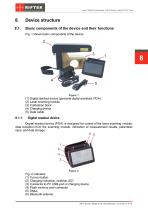
Laser Wheel Profilometer. IKP-5 Series, Model 2016 Year Device structure Basic components of the device and their functions Fig. 1 shows basic components of the device: (1) Digital readout device (personal digital assistant, PDA) (2) Laser scanning module (3) Calibration block (4) Charging device (5) Data cable Digital readout device Digital readout device (PDA) is designed for control of the laser scanning module, data reception from the scanning module, indication of measurement results, parameter input, and data storage. Fig. 2 indicates: (1) Turn-on button (2) Charging indication, red/blue...
Open the catalog to page 8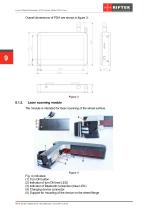
Laser Wheel Profilometer. IKP-5 Series, Model 2016 Year Overall dimensions of PDA are shown in figure 3: Laser scanning module The module is intended for laser scanning of the wheel surface. Fig. 4 indicates: (1) Turn ON button (2) Indicator of turn ON (red LED) (3) Indicator of Bluetooth connection (blue LED) (4) Charging device connector (5) Support for mounting of the device on the wheel flange IKP-5 Series, Model 2016 Year [Revision 3.0.0] 04.01.2016
Open the catalog to page 9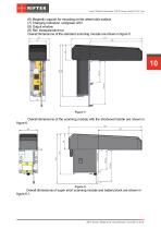
Laser Wheel Profilometer. IKP-5 Series, Model 2016 Year (6) Magnetic support for mounting on the wheel side surface (7) Charging indication, red/green LED (8) Output window (9) Rim measurement rod Overall dimensions of the standard scanning module are shown in figure 5. Overall dimensions of the scanning module with the shortened handle are shown in figure 6. Overall dimensions of super short scanning module and battery block are shown in figure 6.1. IKP-5 Series, Model 2016 Year [Revision 3.0.0] 04.01.2016
Open the catalog to page 10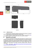
Laser Wheel Profilometer. IKP-5 Series, Model 2016 Year Calibration block Calibration block is intended for calibration and tests of the profilometer. Calibration block is a metal imitator of the part of wheel with a definite profile. Overall dimensions of calibration block are shown in figure 1A of paragraph 30.3. Also possible is supply of a unit with a profile made to the customer’s drawings. Operation principle Operator mounts the laser scanning module onto the wheel to be measured. Having received a command from PDA or PC, the laser module performs non-contact scanning of the wheel surface....
Open the catalog to page 11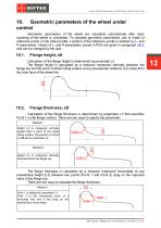
Laser Wheel Profilometer. IKP-5 Series, Model 2016 Year 10. Geometric parameters of the wheel under control Geometric parameters of the wheel are calculated automatically after laser scanning of the wheel is completed. To calculate geometric parameters, use is made of reference points on the wheel profile. Location of the reference points is defined by L- and P-parameters. Values of L- and P-parameters preset in PDA are given in paragraph 14.4. and can be changed by the user. Calculation of the flange height is determined by parameter L2. The flange height is calculated as a distance measured...
Open the catalog to page 12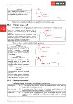
Laser Wheel Profilometer. IKP-5 Series, Model 2016 Year Method 2 Point 1 is defined by parameter L3. Point 2 is the intersection point of a horizontal line and the flange surface. Note: Both calculation methods can be performed simultaneously. Flange slope, qR Calculation of the flange slope is determined by parameters L1 and L3 (or L4). Height L1 is measured vertically downward from the flange top and determines Point 3 on the flange surface. Height L4 is measured vertically upward from a point of the wheel rolling surface, the position of which is defined by parameter L2 (wheel rolling circle),...
Open the catalog to page 13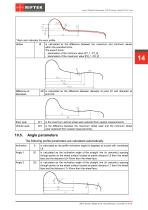
Laser Wheel Profilometer. IKP-5 Series, Model 2016 Year * Red color indicates the worn profile Hollow is calculated as the difference between the maximum and minimum values within the specified limits. The search limits: - parameters of the minimum value [P7_1..P7_2] - parameters of the maximum value [P8_1..P8_2] dD is calculated as the difference between diameter at point D1 and diameter at point D2. Even wear is the maximum vertical wheel wear selected from several measurements. Uneven wear is the difference between the maximum wheel wear and the minimum wheel wear (selected from several measurements)....
Open the catalog to page 14All RIFTEK EUROPE catalogs and technical brochures
 PRODUCT CATALOG 2025
44 Pages
 RF603 Series Manual
49 Pages
 RF602 Series Manual
33 Pages
 RF603HS Series Manual
36 Pages
 RF609 (RF609Rt) Series Manual
33 Pages
 RF600 Series Manual
46 Pages
 RF605 Series Manual
29 Pages
 RF60i Series Manual
46 Pages
 RF62x Manual
174 Pages
 RF25x Series Manual
34 Pages
 RF651 Series Manual
32 Pages
 RF656 Series Manual
32 Pages
 RF656XY Series Manual
33 Pages
 Laser probes Manual
14 Pages
 Pipe ID Control System Manual
18 Pages
 Edge Sensor RF659 Series Manual
25 Pages
 RF627Smart-Weld manual
103 Pages
 PRODUCT CATALOG 2024
40 Pages


- Measuring device
- RIFTEK measuring system
- Windows software
- Industrial software
- Measurement software
- Position transducer
- Sorting machine
- Linear position transmitter
- Digital gauge
- Displacement transducer
- Linear displacement sensor
- RIFTEK micrometer
- Automatic sorting system
- RIFTEK automatic measuring system
- Inspection machine
- RIFTEK optical measuring system
- Linear encoder
- No-contact position sensor
- RIFTEK 3D scanner
- High-precision measurement system