- Catalogs
- RIFTEK EUROPE
- Multichannel Displacement Measurement System RF305 Series Manual
- Company
- Products
- Catalogs
- News & Trends
- Exhibitions
Multichannel Displacement Measurement System RF305 Series Manual
1 /30Pages

Multichannel Displacement Measurement System RF305 Series Manual
1 /30Pages
Catalog excerpts

MULTICHANNEL DISPLACEMENT MEASUREMENT SYSTEM RF305 Series User's manual www.riftek.com [email protected]
Open the catalog to page 1
Multichannel Displacement Measurement System. RF305 Series
Open the catalog to page 2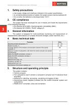
Multichannel Displacement Measurement System. RF305 Series Safety precautions · Use supply voltage and interfaces indicated in the system specifications. · In connection/disconnection of cables, the system power must be switched off. · Do not allow the batteries to discharge below 10.8 V. The system has been developed for use in industry and meets the requirements of the following Directives: · EU directive 2014/30/EU. Electromagnetic compatibility (EMC). · EU directive 2011/65/EU, “RoHS“ category 9. General information The system is designed for multi-coordinate monitoring and measurement of...
Open the catalog to page 3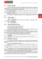
Multichannel Displacement Measurement System. RF305 Series Central computer The central computer of the system is designed to receive data from subsystems remotely and to control subsystems via the wireless communication channel (radio channel 900 MHz), as well as to process these data. The coverage distance of the wireless communication channel of the central computer is not less than 500 m. The central computer of the system is equipped with an autonomous power supply (battery), has a switch. The battery life is not less than 10 hours when two subsystems are connected. The computer is charged...
Open the catalog to page 4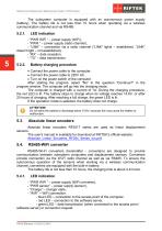
Multichannel Displacement Measurement System. RF305 Series The subsystem computer is equipped with an autonomous power supply (battery). The battery life is not less than 10 hours when operating via a wireless communication channel and via RS485. - “PWR WiFi ” – power supply (WiFi), - “PWR ” – power supply (radio channel), - “LINK” – connection via a radio channel (“LINK” lights – established, “LINK” doesn't light – not established), - “RX” – data reception, - “TX” – data transmission. Battery charging procedure · Connect the power cable to the computer. · Connect the power cable to 220V AC....
Open the catalog to page 5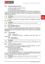
Multichannel Displacement Measurement System. RF305 Series Battery charging procedure · Connect the adapter 15V to the converter. · Connect the adapter to 220V. · Turn on the power switch of the converter. The converter will go into the charging mode. The converter is charged with a current of 0,25А. During the charging procedure, the red LED is lit. The battery stops to charge when its voltage reaches 14.6V, or after 6 hours of charging. After reaching a full charge, the green LED is lit. ATTENTION! During the charging procedure, the Wi-Fi connection to the subsystem computer must not be established....
Open the catalog to page 6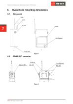
Multichannel Displacement Measurement System. RF305 Series Overall and mounting dimensions Computers
Open the catalog to page 7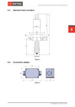
Multichannel Displacement Measurement System. RF305 Series Absolute linear encoders Connection adapter
Open the catalog to page 8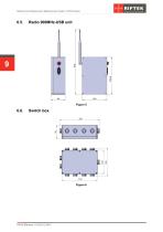
Multichannel Displacement Measurement System. RF305 Series
Open the catalog to page 9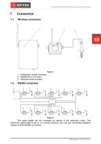
Multichannel Displacement Measurement System. RF305 Series Connection Wireless connection 1 – Subsystem central computer. 2 – RS485-Wi-Fi converter. 3 – Absolute linear encoder. The cable length can be increased by means of the extension cords. The maximum cable length is 20 m. To connect sensors, you can use connecting adapters instead of WiFi-RS485 converters.
Open the catalog to page 10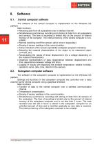
Multichannel Displacement Measurement System. RF305 Series Software Central computer software The software of the central computer is implemented on the Windows CE platform. Main functions: · Receiving data from all subsystems over a wireless channel. · Simultaneous synchronous recording and storing of data from all subsystems and sensors. The time of recording is limited only by the amount of internal memory of the computer. The internal memory of the central computer is nonvolatile. · Remote switching on/off the sensors (all at once or separately). · Zeroing of sensor readings in the current...
Open the catalog to page 11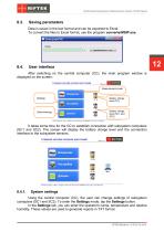
Multichannel Displacement Measurement System. RF305 Series Saving parameters Data is saved in the text format and can be exported to Excel. To convert the files to Excel format, use the program converterMSIP.exe. User interface After switching on the central computer (CC), the main program window is displayed on the screen: It takes some time for the CC to establish connection with subsystem computers (SC1 and SC2). The screen will display the battery charge level and the connection interface to the subsystem sensors. System settings Using the central computer (CC), the user can change settings...
Open the catalog to page 12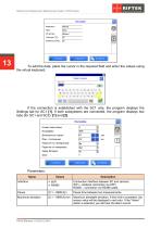
Multichannel Displacement Measurement System. RF305 Series To edit the data, place the cursor in the required field and enter the values using the virtual keyboard. If the connection is established with the SC1 only, the program displays the Settings tab for SC1 [1]. If both subsystems are connected, the program displays two tabs (for SC1 and SC2): [1] and [2]. Parameters: Name Connection interface between SC and sensors. WiFi – wireless connection via WiFi; RS485 – connection via RS485 cable. Pause time between two measurements. Maximum deviation Maximum allowable deviation. If this limit is...
Open the catalog to page 13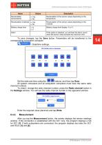
Multichannel Displacement Measurement System. RF305 Series Recalculation of the sensor values depending on the temperature. Recalculation of the sensor values depending on the material. Recalculation (temperature) Battery charge level Battery charge level display: % or V. If this option is selected, you will hear the alarm sound when the sensor value exceeds the maximum limit. To save changes, tap the Save button. Parameters will be transferred to the corresponding subsystem computer. - Date/time settings. Set the date and time using the buttons, and then tap Save. All system computers and all...
Open the catalog to page 14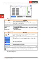
Multichannel Displacement Measurement System. RF305 Series Sensor ordinal number in the subsystem [1..10]. power monitor # If the connection interface is WiFi, the serial number of the detected power monitor (WiFi module) is displayed. Sensor serial number. Current sensor temperature. If the Recalculation (material) option is selected, the button with the material type is displayed. Current sensor readings. Other elements: Name Description Battery charge level and connection interface of the current subsystem. Display / do not display the sensor readings. Connect / disconnect the sensors. When...
Open the catalog to page 15All RIFTEK EUROPE catalogs and technical brochures
 PRODUCT CATALOG 2025
44 Pages
 RF603 Series Manual
49 Pages
 RF602 Series Manual
33 Pages
 RF603HS Series Manual
36 Pages
 RF609 (RF609Rt) Series Manual
33 Pages
 RF600 Series Manual
46 Pages
 RF605 Series Manual
29 Pages
 RF60i Series Manual
46 Pages
 RF62x Manual
174 Pages
 RF25x Series Manual
34 Pages
 RF651 Series Manual
32 Pages
 RF656 Series Manual
32 Pages
 RF656XY Series Manual
33 Pages
 Laser probes Manual
14 Pages
 Pipe ID Control System Manual
18 Pages
 Edge Sensor RF659 Series Manual
25 Pages
 RF627Smart-Weld manual
103 Pages
 PRODUCT CATALOG 2024
40 Pages


- Measuring device
- RIFTEK measuring system
- Windows software
- Industrial software
- Measurement software
- Position transducer
- Sorting machine
- Linear position transmitter
- Digital gauge
- Displacement transducer
- RIFTEK micrometer
- Linear displacement sensor
- Automatic sorting system
- RIFTEK automatic measuring system
- RIFTEK optical measuring system
- Inspection machine
- No-contact position sensor
- High-precision measurement system
- RIFTEK 3D scanner