- Catalogs
- RIFTEK EUROPE
- Laser System for Inline Sheet Materials Thickness Measurement RF160.20 Manual
- Company
- Products
- Catalogs
- News & Trends
- Exhibitions
Laser System for Inline Sheet Materials Thickness Measurement RF160.20 Manual
1 /25Pages

Laser System for Inline Sheet Materials Thickness Measurement RF160.20 Manual
1 /25Pages
Catalog excerpts

THICKNESS MEASUREMENT SYSTEM RF160.20 Series User's manual www.riftek.com [email protected]
Open the catalog to page 1
Thickness Measurement System. RF160.20 Series
Open the catalog to page 2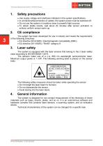
Thickness Measurement System. RF160.20 Series Safety precautions · · · · Use supply voltage and interfaces indicated in the system specifications. In connection/disconnection of cables, the system power must be switched off. Do not use the system in locations close to powerful light sources. To obtain stable results, wait about 20 minutes after sensor activation to achieve uniform sensor warm-up. The system has been developed for use in industry and meets the requirements of the following Directives: · EU directive 2014/30/EU. Electromagnetic compatibility (EMC). · EU directive 2011/65/EU, “RoHS“...
Open the catalog to page 3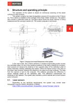
Thickness Measurement System. RF160.20 Series Structure and operating principle The operation of the system is based on continuous scanning of the sheet surfaces by laser sensors. The system contains two laser triangulation sensors (2) mounted on the C-frame (3). The C-frame is installed on the carriage of the linear motion module (4). The system also contains a calibration plate (6). The figure below shows the sheet material (1) being measured and the conveyor section (5). The control computer is not shown. Figure 1. Structure and overall dimensions of the system In the main mode, the C-frame...
Open the catalog to page 4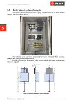
Thickness Measurement System. RF160.20 Series Control cabinet and panel computer The control cabinet contains a power supply, a motor driver for the linear motion system, and an Ethernet switch. The industrial panel computer is designed to receive information from sensors, analyze and display measurement results. Overall and mounting dimensions of the control cabinet and panel computer are shown in Figure 2. Figure 2. Control cabinet and panel computer
Open the catalog to page 5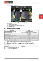
Thickness Measurement System. RF160.20 Series Panel computer connectors: 6 Figure 3. Panel computer connectors Designations: 1 – Display power cable. 2 – Data cable for connection to COM1 port. 3 – Ethernet cable. Basic technical data Parameter Thickness measurement range, mm Measurement error, um Scanning range, mm Input interface for sensors connection Measurement speed, kHz Power supply, V Power consumption, not more, W Operating Ambient temperature, °С conditions Relative humidity, % Value 10 or 25 or customized ±3 (for 10 mm range) or ±7 (for 27 mm range) or customized by request Ethernet...
Open the catalog to page 6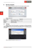
Thickness Measurement System. RF160.20 Series Service program After powering on the panel computer, the main program window appears: 7 Buttons assignment: Button Settings Measurement Calibration Database Assignment Open the "Settings" window. Open the "Thickness measurement" window. Calibrate the system. Browse the database. Before starting to work with the system, it is necessary to configure parameters. Tap the Settings button in the main window.The program will ask for a password. When initially installed, the program accepts the following password: 1111. Enter the password and tap Ok.
Open the catalog to page 7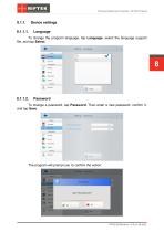
Thickness Measurement System. RF160.20 Series Device settings To change the program language, tap Language, select the language support file, and tap Select. To change a password, tap Password. Then enter a new password, confirm it, and tap Save. The program will prompt you to confirm the action:
Open the catalog to page 8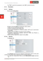
Thickness Measurement System. RF160.20 Series Tap "Yes" to save the new password, or tap "No" to cancel the action. В области настроек Sensor пользователь может указать: · СОМ порт для подключения датчиков. · Скорость передачи данных (Baud rate). · Если данные передаются по Ethernet, выбрать UDP порт (по умолчанию всегда 603). В области настроек Driver пользователь может выбрать: · Интерфейс подключения драйвера двигателя RS485 или Ethernet и указать порт подключения. Чтобы сохранить изменения, нажмите кнопку Save.
Open the catalog to page 9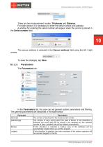
Thickness Measurement System. RF160.20 Series There are two measurement modes: Thickness and Distance. For each sensor, it is necessary to enter the serial number and address. A window for entering the serial number will appear when the cursor is placed in the Serial number field. 10 The sensor address is selected in the Sensor address field using the left / right arrows. To save the changes, tap Save. In the Parameters tab, the user can set general system parameters and filtering. The general parameters are described in the table below. Parameter Decimals Data Storage Backup Logging Description...
Open the catalog to page 10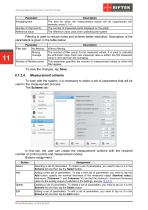
Thickness Measurement System. RF160.20 Series Parameter Averaging time Number of chart points Reference value Description The time for which the measurement results will be output/saved (for example, every 0.1 s). The number of measured points displayed on the graph. The reference value used when calibrating the system. Filtering is used to reduce noise and achieve better resolution. Description of the parameters is given in the table below: Parameter Filter type No filtering Moving Average Number of filtration points Description Without filtering. The number of filter points for the measured...
Open the catalog to page 11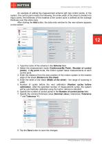
Thickness Measurement System. RF160.20 Series An example of adding the measurement scheme with two control points. In the system, the control point means the following: the entire width of the sheet is divided into equal zones, the thickness of the material at the control point is defined as the average thickness over the entire zone. After clicking the Add button, the data entry window for the new scheme appears on the screen: 1. Type the name of the scheme in the Scheme field. 2. Select the measurement mode (Continuous/By Point). (Number of control points). In By point mode, the motion system...
Open the catalog to page 12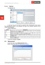
Thickness Measurement System. RF160.20 Series In this tab, the user can enter the operator's data. Subsequently, when saving the measurement results to the database, the data of the selected operator will be written to the database. Buttons assignment: Button Select Assignment Selecting the current operator. To select the current operator, tap on the personnel number and then tap the Select button. Adding a new operator. To add a new operator, tap the Add button, specify the personnel number, last name and first name of the operator. Deleting the operator. To delete the operator, tap on the personnel...
Open the catalog to page 13All RIFTEK EUROPE catalogs and technical brochures
 PRODUCT CATALOG 2025
44 Pages
 RF603 Series Manual
49 Pages
 RF602 Series Manual
33 Pages
 RF603HS Series Manual
36 Pages
 RF609 (RF609Rt) Series Manual
33 Pages
 RF600 Series Manual
46 Pages
 RF605 Series Manual
29 Pages
 RF60i Series Manual
46 Pages
 RF62x Manual
174 Pages
 RF25x Series Manual
34 Pages
 RF651 Series Manual
32 Pages
 RF656 Series Manual
32 Pages
 RF656XY Series Manual
33 Pages
 Laser probes Manual
14 Pages
 Pipe ID Control System Manual
18 Pages
 Edge Sensor RF659 Series Manual
25 Pages
 RF627Smart-Weld manual
103 Pages
 PRODUCT CATALOG 2024
40 Pages


- Measuring device
- RIFTEK measuring system
- Windows software
- Industrial software
- Measurement software
- Position transducer
- Sorting machine
- Linear position transmitter
- Digital gauge
- Displacement transducer
- RIFTEK micrometer
- Linear displacement sensor
- Automatic sorting system
- RIFTEK automatic measuring system
- RIFTEK optical measuring system
- Inspection machine
- No-contact position sensor
- High-precision measurement system
- Linear encoder
- RIFTEK 3D scanner