- Catalogs
- RIFTEK EUROPE
- Laser speed and length sensors ISD-5 Series Manual
- Company
- Products
- Catalogs
- News & Trends
- Exhibitions
Laser speed and length sensors ISD-5 Series Manual
1 /18Pages

Laser speed and length sensors ISD-5 Series Manual
1 /18Pages
Catalog excerpts

LASER SPEED AND LENGTH SENSORS ISD-5-M+ Series User's manual www.riftek.com [email protected]
Open the catalog to page 1
Laser Speed And Length Sensors. ISD-5-M+ Series
Open the catalog to page 2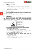
Laser Speed And Length Sensors. ISD-5-M+ Series Safety precautions · · · · Use supply voltage and interfaces indicated in the sensor specifications. In connection/disconnection of cables, the sensor power must be switched off. Do not use sensors in locations close to powerful light sources. To obtain stable results, wait about 20 minutes after sensor activation to achieve uniform sensor warm-up. The sensors have been developed for use in industry and meet the requirements of the following Directives: · EU directive 2014/30/EU. Electromagnetic compatibility (EMC). · EU directive 2011/65/EU, “RoHS“...
Open the catalog to page 3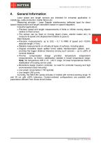
Laser Speed And Length Sensors. ISD-5-M+ Series General Information Laser speed and length sensors are intended for industrial application in metallurgy, cable production, textile fabrics etc. Measuring principle – Laser Doppler interferometry (reflected type) for direct speed measurement and length calculation based on speed integration. Industrial applications: · Precision speed and length measurements of finite or infinite moving objects relative to fixed sensor. · The sensor can be fixed on moving object (crane, electric loader etc.) to measure its speed and displacement relative to ground....
Open the catalog to page 4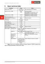
Laser Speed And Length Sensors. ISD-5-M+ Series Basic technical data Parameter Speed range, m/min Speed accuracy, % RMS Measuring frequency, Hz Nominal distance to the object, ± tolerance, сm Emitter type Power supply, Vs Power consumption Temperature working range, С Sensor weight, g Sensor size, mm Sensor environmental protection Sensor output Frequency out Physical data latency at measurement freq, ms 54 Hz Base Software Notes User selectable (see User Manual). No signal averaging. With averaging 0,2...0,3 s at V > 1 m/s. Precalibration is needed to reject the geometric errors of sensor mounting....
Open the catalog to page 5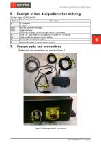
Laser Speed And Length Sensors. ISD-5-M+ Series Example of item designation when ordering Description St – Standard. Lt – Mini. Nominal distance to the object. Digital interfaces: COM-USB converter. Others (old style RS232…) on request. Pulse out – base. Analog out, voltage (U) or current (I) – on request. Cable length from sensor to custom system. Sensor with in-built heater (option). Sensor with protect air cooling housing (option). System parts and connections System parts and connections are shown in Figure 1. Figure 1. Sensor parts and connectors.
Open the catalog to page 6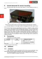
Laser Speed And Length Sensors. ISD-5-M+ Series Overall demands for sensor mounting Mounting holes sizes and sensor axes relative to moving object are shown in Figure 2. Sensor position relative to moving object along Z-axis. Mounting holes: 127x30mm. Nominal distance to the object could be measured from front plane of the sensor. Sensor X-axis must be perpendicular and Z-axis – parallel to object moving direction. In ZY plane (perpendicular to drawing plane) sensor Y-axis can be tilted from vertical position (for instance, to avoid the light direct reflection to sensor receiver area from glossy...
Open the catalog to page 7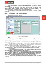
Laser Speed And Length Sensors. ISD-5-M+ Series - Run-Time Engine for support LabView *exe programs. Run Setup in directory “ISD Installer”. - LV Visa to get access to PC ports, including COM. For Win <7 install visa320runtime, for >=7 - visa540_runtime. Note: only one must be installed! If you install wrong version – uninstall it before other version installation. - COM-USB Driver for Prolific PL2303HX. For Win 8/10 old v.1.5.0 (10.21.2011) works well. Program ISD_COM read description Open program ISD_COM read.exe. Figure 3. Program window. Here: 1 – Run program button . When it runs the indicator...
Open the catalog to page 8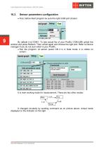
Laser Speed And Length Sensors. ISD-5-M+ Series Sensor parameters configuration · First, before Start program be sure the right COM port chosen: By default it is COM1. To see actual No of your Prolific COM-USB unfold the window and press Refresh. Then unfold again and choose the right port. Refer to Device manager if you do not sure which is your Prolific. · Run the program. At sensor power ON it is in Data mode, it is visible on screen: It is main working mode for measurement. There are two other modes: It changed circularly by sending command as on picture above. Actual mode displayed on the...
Open the catalog to page 9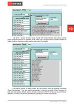
Laser Speed And Length Sensors. ISD-5-M+ Series 10 1-st Send : sensor in Data mode. Along with measurement data sensor sends array of signal spectrum, it appears on tab Test. Use it to ajust sensor position relative to object to get a maximum signal quality (see below for details). 2-nd Send: sensor in Setup mode. On the picture: result of sending command “Read Parameters”. You see actual parameters in sensor controller Flash memory (at first read it is factory default, save it as text or picture in the PC to have a copy of factory defaults). Full list of command unfolded by pointing to window...
Open the catalog to page 10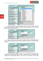
Laser Speed And Length Sensors. ISD-5-M+ Series List of Commands. First, edit parameters value you want to change (on the left column (default values, they appears as default at first program Run), then send it by appropriate Command one by one: Result of sending command. Now the parameter value is in operating memory of sensor controller. Change other parameters if needed, then write it in controller Flash memory: All parameters has written to Flash. You can check it by command Read Parameters. Then change the Mode to “Data” – sensor is ready for measuring. Note: actually, Pulce output always...
Open the catalog to page 11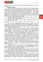
Laser Speed And Length Sensors. ISD-5-M+ Series controller is very busy, which lead to reducing measurement frequency and some data may distorted. Parameters details: - SNR_LIM1 и SNR_LIM2 – Signal to Noise Ratio Limit – to distinguish between stand-still and mowing object. If real values less – speed regarded as = 0. Typical values at stand still are 2 – 6. At moving object S/N 1 (and S/N 2 at velocities > 20% of Vmax) > 100 - 1000 typically. See real S/N at stand still/ no object and set it 5 – 10 times more to guarantee V=0 at stand still. But in some cases (vibrating object or by-side mowing...
Open the catalog to page 12All RIFTEK EUROPE catalogs and technical brochures
 PRODUCT CATALOG 2025
44 Pages
 RF603 Series Manual
49 Pages
 RF602 Series Manual
33 Pages
 RF603HS Series Manual
36 Pages
 RF609 (RF609Rt) Series Manual
33 Pages
 RF600 Series Manual
46 Pages
 RF605 Series Manual
29 Pages
 RF60i Series Manual
46 Pages
 RF62x Manual
174 Pages
 RF25x Series Manual
34 Pages
 RF651 Series Manual
32 Pages
 RF656 Series Manual
32 Pages
 RF656XY Series Manual
33 Pages
 Laser probes Manual
14 Pages
 Pipe ID Control System Manual
18 Pages
 Edge Sensor RF659 Series Manual
25 Pages
 RF627Smart-Weld manual
103 Pages
 PRODUCT CATALOG 2024
40 Pages


- Measuring device
- RIFTEK measuring system
- Windows software
- Industrial software
- Measurement software
- Position transducer
- Sorting machine
- Linear position transmitter
- Digital gauge
- Displacement transducer
- RIFTEK micrometer
- Linear displacement sensor
- Automatic sorting system
- RIFTEK automatic measuring system
- RIFTEK optical measuring system
- Inspection machine
- No-contact position sensor
- High-precision measurement system
- Linear encoder
- RIFTEK 3D scanner