- Catalogs
- RIFTEK EUROPE
- Johnson filters inspection machine Manual
- Company
- Products
- Catalogs
- News & Trends
- Exhibitions
Johnson filters inspection machine Manual
1 /21Pages

Johnson filters inspection machine Manual
1 /21Pages
Catalog excerpts

WIRE FILTER SLOT GAPS INSPECTION MACHINE Series User's manual www.riftek.com [email protected]
Open the catalog to page 1
Wire Filter Slot Gaps Inspection Machine
Open the catalog to page 2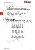
Wire Filter Slot Gaps Inspection Machine 1. Safety precautions · Only persons who have studied this User's Manual are allowed to operate the Wire Filter Slot Gaps Inspection Machine (hereinafter referred to as the "machine"). · Use supply voltage and interfaces indicated in the specification. · When connecting/disconnecting cables, the machine must be powered off. The machine has been developed for use in industry and meets the requirements of the following Directives: · EU directive 2014/30/EU. Electromagnetic compatibility (EMC). · EU directive 2011/65/EU, “RoHS“ category 9. 3. General information...
Open the catalog to page 3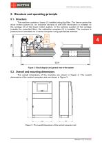
Wire Filter Slot Gaps Inspection Machine 5. Structure and operating principle 5.1. Structure The machine contains a frame (1) installed along the filter. The frame carries the linear motion system (2). An industrial camera (4) with LED illumination is installed on the carriage (3) of the linear motion system. In the extreme position of the carriage (outside the controlled filter), the calibration template (5) is installed. The machine is powered and controlled via a central computer using specialized software. Figure 2 - Block diagram and general view of the system 5.2. Overall and mounting dimensions...
Open the catalog to page 4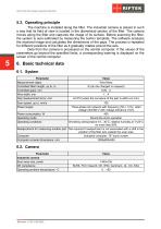
Wire Filter Slot Gaps Inspection Machine 5.3. Operating principle The machine is installed along the filter. The industrial camera is placed in such a way that its field of view is located in the diametrical section of the filter. The camera moves along the filter and captures the image of its surface. Before scanning the filter, the system is auto-calibrated by measuring the built-in template. The software analyzes the received image and calculates the dimensions of the gaps. The process is repeated for different positions of the filter as it gradually rotates around the axis. Data from the...
Open the catalog to page 5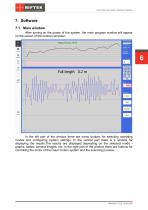
Wire Filter Slot Gaps Inspection Machine 7. Software 7.1. Main window After turning on the power of the system, the main program window will appear on the screen of the central computer: In the left part of the window there are menu buttons for selecting operating modes and configuring system settings. In the central part there is a window for displaying the results.The results are displayed depending on the selected mode graphs, tables, camera images, etc. In the right part of the window there are buttons for controlling the motor of the linear motion system and the scanning process.
Open the catalog to page 6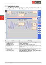
Wire Filter Slot Gaps Inspection Machine 7.2. "Measurement" section The Measurement section is designed to display the measurement results and control the geometric parameters of wire filter gaps. "Gap size graph" panel Displays the measured width of the wire filter gaps. "Focus graph" panel Displays the focus quality. "Measurement" button Designed to go to the "Measurement" section. "Information" panel Displays the current system settings (product type, tolerances, operator name). "Current item" panel Displays the serial number of the item being measured. "Mode" checkbox Sets the operating mode:...
Open the catalog to page 7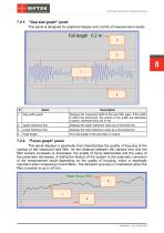
Wire Filter Slot Gaps Inspection Machine 7.2.1. "Gap size graph" panel This panel is designed for graphical display and control of measurement results. Displays the measured width of the wire filter gaps. If the width is within the tolerances, the points on the graph are displayed in green, otherwise they are in red. Upper tolerance line Displays the upper tolerance value as a horizontal line. Lower tolerance line Displays the lower tolerance value as a horizontal line. Total length The total length of the wire filter in meters. 7.2.2. "Focus graph" panel This panel displays a parameter that...
Open the catalog to page 8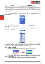
Wire Filter Slot Gaps Inspection Machine Focus value graph This parameter characterizes the quality of focus. Nominal focus level The level is estimated automatically and affects the amount of focus correction that can be enabled in the settings. Mean focus value Displays the mean focus value. 7.2.3. "Information" panel This panel displays the measured width of the wire filter gaps, product type, and operator's name. Settings can be changed in the Settings menu (see Main window). 7.2.4. "Current item" panel This panel displays the serial number of the measured product under which it will be stored...
Open the catalog to page 9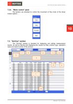
Wire Filter Slot Gaps Inspection Machine 7.2.6. "Motor control" panel The buttons are intended to control the movement of the motor of the linear motion system. 7.3. "Archive" section The "Archive" section is intended for displaying and editing measurement results, as well as filtering and displaying the results by date, product type, operator's name and serial number of the product.
Open the catalog to page 10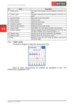
Wire Filter Slot Gaps Inspection Machine «Table» panel The latest measurements from the database in the form of a table. «Graph» panel The latest measurements from the database in the form of a graph. «Archive» button Menu button to go to this section. «Date» element «Type» element Filtering by product type. «Operator» element «Serial number» element Filtering by product serial number. «Reset» button Reset filters (4)-(7) and display the latest measurements. «Select» checkbox Selected database records will be displayed in (1) and (2), and can also be deleted (10) or printed as a report (11)....
Open the catalog to page 11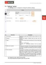
Wire Filter Slot Gaps Inspection Machine 7.4. "Settings" section The Settings section is designed to change the software settings. Product type Selecting the product type. Possible values are taken from the database. Selecting the operator. Possible values are taken from the database. Setting the nominal value and tolerances for the wire filter gap width. Fields: Width, mm - nominal value. Tolerance "+/-" - permissible deviations from the nominal value. Motion blur correction The amount of correction of the measured value due to image blur during the movement of the camera along the wire filter....
Open the catalog to page 12All RIFTEK EUROPE catalogs and technical brochures
 PRODUCT CATALOG 2025
44 Pages
 RF603 Series Manual
49 Pages
 RF602 Series Manual
33 Pages
 RF603HS Series Manual
36 Pages
 RF609 (RF609Rt) Series Manual
33 Pages
 RF600 Series Manual
46 Pages
 RF605 Series Manual
29 Pages
 RF60i Series Manual
46 Pages
 RF62x Manual
174 Pages
 RF25x Series Manual
34 Pages
 RF651 Series Manual
32 Pages
 RF656 Series Manual
32 Pages
 RF656XY Series Manual
33 Pages
 Laser probes Manual
14 Pages
 Pipe ID Control System Manual
18 Pages
 Edge Sensor RF659 Series Manual
25 Pages
 RF627Smart-Weld manual
103 Pages
 PRODUCT CATALOG 2024
40 Pages


- Measuring device
- RIFTEK measuring system
- Windows software
- Industrial software
- Measurement software
- Position transducer
- Sorting machine
- Linear position transmitter
- Digital gauge
- Displacement transducer
- RIFTEK micrometer
- Linear displacement sensor
- Automatic sorting system
- RIFTEK automatic measuring system
- RIFTEK optical measuring system
- No-contact position sensor
- High-precision measurement system
- Linear encoder
- RIFTEK 3D scanner