- Catalogs
- RIFTEK EUROPE
- Gypsum plasterboard geometry control system 3DGypsumB Series Manual
- Company
- Products
- Catalogs
- News & Trends
- Exhibitions
Gypsum plasterboard geometry control system 3DGypsumB Series Manual
1 /36Pages

Gypsum plasterboard geometry control system 3DGypsumB Series Manual
1 /36Pages
Catalog excerpts
GYPSUM PLASTERBOARD GEOMETRY CONTROL SYSTEM 3DGypsumB Series User's manual www.riftek.com [email protected]
Open the catalog to page 1
Gypsum Plasterboard Geometry Control System
Open the catalog to page 2
Gypsum Plasterboard Geometry Control System
Open the catalog to page 3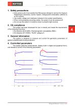
Gypsum Plasterboard Geometry Control System 1. Safety precautions · Only persons who have studied this Manual are allowed to service the Gypsum Plasterboard Geometry Control System 3DGypsumB (hereinafter referred to as the system). · Use supply voltage and interfaces indicated in the system specifications. · When connecting/disconnecting cables, the system must be powered off. · Do not use the system in locations close to powerful light sources. 2. CE сompliance The system has been developed for use in industry and meets the requirements of the following Directives: · EU directive 2014/30/EU....
Open the catalog to page 4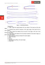
Gypsum Plasterboard Geometry Control System Figure 1 - Controlled parameters Designations: А - Edge angle (the angle between the top surface of the board and the side edge). В - Shoulder (the maximum deviation of the upper edge of the board from its main surface). С - Taper length (the distance from the start of the edge to the end of the thinning of the edge). D - Taper depth (the distance from the bottom baseline to the bottom edge at a given horizontal position). E - Board width (the distance between the board edges). F - Board thickness. G - Rim. H - Groove. I - Raising/lowering (lifting)...
Open the catalog to page 5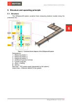
Gypsum Plasterboard Geometry Control System 5. Structure and operating principle 5.1. Structure The 3DGypsumB system contains three measuring stations located along the production line. Figure 2 - Functional block diagram of the 3DGypsumB system Designations: 1 – Measuring station 1. 2 – Measuring station 2. 3 – Measuring station 3. 4 – Additional operator terminal. 5 – Central computer. A – Mixer / molding. В – Slicing. Red lines – 24V power supply (generated by the system). Green lines – Ethernet network of the system.
Open the catalog to page 6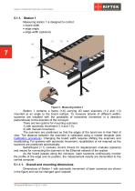
Gypsum Plasterboard Geometry Control System 5.1.1. Station 1 Measuring station 1 is designed to control: · board width, · edge angle, · edge width (optional). Figure 3 - Measuring station 1 Station 1 contains a frame (1.6) carrying 2D laser scanners (1.2 and 1.3) mounted at an angle to the board surface. To measure boards of different widths, scanners are installed with the possibility of transverse movement in a direction perpendicular to the direction of the conveyor. There are two options for mounting scanners: 1) with automatic movement (1.4 and 1.5), 2) with manual movement. The scanners...
Open the catalog to page 7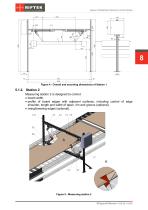
Gypsum Plasterboard Geometry Control System Figure 4 - Overall and mounting dimensions of Station 1 5.1.2. Station 2 Measuring station 2 is designed to control: · board width, · profile of board edges with adjacent surfaces, including control of edge shoulder, length and width of taper, rim and groove (optional), · rising/lowering edges (optional). Figure 5 - Measuring station 2
Open the catalog to page 8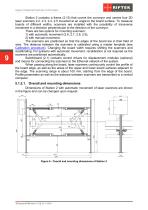
Gypsum Plasterboard Geometry Control System Station 2 contains a frame (2.10) that covers the conveyor and carries four 2D laser scanners 2.2, 2.3, 2.4, 2.5 mounted at an angle to the board surface. To measure boards of different widths, scanners are installed with the possibility of transverse movement in a direction perpendicular to the direction of the conveyor. There are two options for mounting scanners: 1) with automatic movement (2.6, 2.7, 2.8, 2.9), 2) with manual movement. The scanners are positioned so that the edges of the board are in their field of view. The distance between the...
Open the catalog to page 9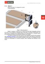
Gypsum Plasterboard Geometry Control System 5.1.3. Station 3 Measuring station 3 is designed to control: · board thickness. Figure 7 - Measuring station 3 Station 3 contains C-frame (3.6), on which two point laser triangulation sensors (3.2 and 3.3) are installed on opposite sides of the board. To prevent contamination, the lower sensor is equipped with a blowing system (3.4). Switchboard (3.1) contains means for connecting the sensors to the Ethernet network of the system. The distance between the laser sensors is pre-calibrated using the tools supplied (see Calibration procedure). When passing...
Open the catalog to page 10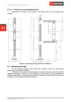
Gypsum Plasterboard Geometry Control System 5.1.3.1. Overall and mounting dimensions Dimensions of Station 3 are shown in the figure and can be changed upon request: Figure 8 - Overall and mounting dimensions of Station 3 5.2. Operating principle As the gypsum boards move along the conveyor, they are continuously measured by the system's sensors. Information from sensors is processed on a central computer using the supplied software (hereinafter referred to as the software). If the values of the parameters are outside of tolerances, a corresponding warning is displayed on the screen of the central...
Open the catalog to page 11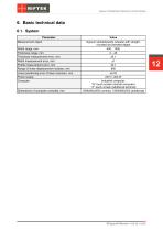
Gypsum Plasterboard Geometry Control System 6. Basic technical data 6.1. System Parameter Measurement object Width range, mm Thickness range, mm Thickness measurement error, mm Width measurement error, mm Profile measurement error, mm Range of linear displacement modules, mm Linear positioning error of laser scanners, mm Power supply Computer Dimensions of computer consoles, mm Value Gypsum plasterboards (sheets) with straight, rounded and beveled edges 400…1400 2…45 ±0.1 ±1 ±0.1 800 ±0.02 220 V, 400 W Industrial computer, 19” touch screen (central computer) 17” touch screen (additional terminal)...
Open the catalog to page 12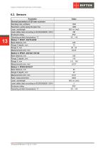
Gypsum Plasterboard Geometry Control System General parameters of 2D laser scanners Sampling rate, profiles/s Resolution, points along the laser line Laser, wavelength Laser safety class according to IEC/EN 60825-1:2014 Enclosure rating Operating ambient temperature, °С Station 1: RF627- 245/70-40/50 Base distance, mm Range Z (depth), mm Range Х, mm Measurement error, mm Station 2: RF627- 245/140-110/140 Base distance, mm Range Х, mm Measurement error, mm Station 3: RF603-80/25-ET Base distance, mm Rate, measurements/s Laser, wavelength Laser safety class according to IEC/EN 60825-1:2014 Enclosure...
Open the catalog to page 13All RIFTEK EUROPE catalogs and technical brochures
 PRODUCT CATALOG 2025
44 Pages
 RF603 Series Manual
49 Pages
 RF602 Series Manual
33 Pages
 RF603HS Series Manual
36 Pages
 RF609 (RF609Rt) Series Manual
33 Pages
 RF600 Series Manual
46 Pages
 RF605 Series Manual
29 Pages
 RF60i Series Manual
46 Pages
 RF62x Manual
174 Pages
 RF25x Series Manual
34 Pages
 RF651 Series Manual
32 Pages
 RF656 Series Manual
32 Pages
 RF656XY Series Manual
33 Pages
 Laser probes Manual
14 Pages
 Pipe ID Control System Manual
18 Pages
 Edge Sensor RF659 Series Manual
25 Pages
 RF627Smart-Weld manual
103 Pages
 PRODUCT CATALOG 2024
40 Pages


- Measuring device
- RIFTEK measuring system
- Windows software
- Industrial software
- Measurement software
- Position transducer
- Sorting machine
- Linear position transmitter
- Digital gauge
- Displacement transducer
- RIFTEK micrometer
- Linear displacement sensor
- Automatic sorting system
- RIFTEK automatic measuring system
- RIFTEK optical measuring system
- Inspection machine
- No-contact position sensor
- High-precision measurement system
- Linear encoder
- RIFTEK 3D scanner