- Catalogs
- RIFTEK EUROPE
- Edge Sensor RF659 Series Manual
- Company
- Products
- Catalogs
- News & Trends
- Exhibitions
Edge Sensor RF659 Series Manual
1 /25Pages

Edge Sensor RF659 Series Manual
1 /25Pages
Catalog excerpts

EDGE SENSORS RF659 Series User's manual www.riftek.com [email protected]
Open the catalog to page 1
Edge Sensors. RF659 Series
Open the catalog to page 2
Edge Sensors. RF659 Series Safety precautions · Use supply voltage and interfaces indicated in the sensor specifications. · In connection/disconnection of cables, the micrometer power must be switched off. · Do not use micrometers in locations close to powerful light sources. · Sensor windows should be kept clean. Do not clean the glass with abrasive and aggressive cleaning agents. · If the windows are accidentally touched with fingers, they should be wiped immediately. The sensors have been developed for use in industry and meet the requirements of the following Directives: · EU directive 2014/30/EU....
Open the catalog to page 3
Edge Sensors. RF659 Series Basic technical data Measuring head Type Distance between transmitter and receiver, mm Measurement range, mm Accuracy, um Repeatability, um Temperature dependence Light source Power supply, V Power consumption, W (transmitter/receiver) Enclosure rating Environment resistance Vibration Shock Operation temperature, °С Relative humidity, % Housing/window material Weight with cable (cable length of 300 mm), gram Overall and mounting dimensions RF659 30 7 ±20 1 0.1% range/С° LED 5 0.5 IP40 20g/10…1000Hz, 6 hours, for each of XYZ axes 30 g / 6 ms -10…+60 5-95 aluminum / glass...
Open the catalog to page 4
Edge Sensors. RF659 Series Type Number of connected heads ("transmitter" - "receiver" pairs) Cycle of result updating, Hz Digital indication Resolution of digital indication, µm Digital output Analog outputs Resolution of analog outputs, µm Logic outputs Power supply, V Power consumption, W Housing material Weight, g Overall and mounting dimensions RF301D 2 1500 two five-digit displays 1, 10 RS485* two isolated channels, ±5V (±10), load >10 kOhm 2 eight isolated channels of npn - open collector 24 1.5 aluminum 200 see the figure * - RS485 is used to diagnose and configure the controller and measuring...
Open the catalog to page 5
Edge Sensors. RF659 Series The back side of the controller contains connectors for measuring heads, 8-pin connector for power, analog outputs and RS485 interface, and 9-pin connector for logical outputs (Fig. 2). Spring connector 1, numbering 'left to right' 1 2 3 4 5 6 7 8 Designation +24V GND Isolated Analog Output 1 Isolated Analog Output 2 AGND DATA+ (RS485) DATA- (RS485) GND Designation Isolated Alarm1 Channel 1 Isolated Alarm2 Channel 1 Isolated Threshold Low1 Isolated Threshold High1 Isolated Alarm1 Channel 2 Isolated Alarm2 Channel 2 Isolated Threshold Low2 Isolated Threshold High2 Isolated...
Open the catalog to page 6
Edge Sensors. RF659 Series Working with parameters Parameter control buttons and LED indicators are placed on the front panel of the controller, Fig. 3. Parametrization is performed for each channel separately. Press the Channel button to select the channel. Selected channel is indicated by the corresponding LED. Settings menu To enter the settings menu, you need to hold the Menu button pressed for 3 seconds. Zero point This parameter sets the measurement starting point within the measuring range. After Zero Point is set, the measurement result (in the digital display and analog output) is displayed...
Open the catalog to page 7
Edge Sensors. RF659 Series the material edge position. The device has the ability to ignore the technological objects in the measurement process to ensure stable control of the main edge position. Press the Channel button and select the channel. The current channel number is highlighted by LED. Enter the menu, select "tEI.x" using the arrows, and press Enter to enter the submenu. Detection threshold Detection threshold sets a value, going beyond that is considered as the time of technological element detection. The parameter sets positive and negative thresholds simultaneously, i.e. if parameter...
Open the catalog to page 8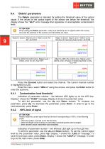
Edge Sensors. RF659 Series 'Debris' parameters The Debris parameter is intended for setting the threshold value of the optical signal. If the values of the optical signal of the sensor are below the threshold, the display shows the "AL2" error message that signalizes of unacceptable contamination level. ATTENTION! When setting the Debris parameter, make sure that there are no objects within the control zone and the windows of the receiver and transmitter are clean. Object is absent. Signal Level > Debris Level. No dirt. AL2=OFF Object is absent. Signal Level < Debris Level. Window of measuring...
Open the catalog to page 9
Edge Sensors. RF659 Series To exit the settings menu, press the Esc button. You will be prompted to exit without saving to FLASH by the "CAnCEL" message. To save parameters to FLASH, select "SAUE" and press Enter. 'Count direction' parameter Default count direction is conducted from top down (Fig. a). If necessary, the count direction can be changed. Press the Channel button and select the channel. The current channel number is highlighted by LED. Enter the menu, select "dIr.x" using the arrows, and press the Enter button in order to enter the submenu. To edit the parameter, use the Up and Down...
Open the catalog to page 10
Edge Sensors. RF659 Series Logic output thresholds The controller is equipped with logical outputs (two logical outputs for each channel). These logical outputs signalize about going beyond the upper and lower measurement thresholds. Press the Channel button and select the channel. The current channel number is highlighted by LED. Enter the menu, select "LOUt.x" using the arrows, and press the Enter button in order to enter the submenu. Lower threshold The Threshold Low logical output is an isolated output of the open collector type (n-p-n). It is set to the active state when the measurement...
Open the catalog to page 11
Edge Sensors. RF659 Series - Press Enter to go to the next parameter. - Display 1 shows the "AOLo.2" message. Display 2 shows the parameter value. - Connect the voltmeter to terminals AO2 and AGnd. - Use the arrow buttons to set the parameter value so that the voltage at the analog output AO2 is set to -5V. - Press Enter to go to the next parameter. - Display 1 shows the "AOHi.2" message. Display 2 shows the parameter value. - Use the arrow buttons to set the parameter value so that the voltage at the analog output AO2 is set to 5V. - Press Enter. - To save the changes, select "SAUE" using the...
Open the catalog to page 12All RIFTEK EUROPE catalogs and technical brochures
 PRODUCT CATALOG 2025
44 Pages
 RF603 Series Manual
49 Pages
 RF602 Series Manual
33 Pages
 RF603HS Series Manual
36 Pages
 RF609 (RF609Rt) Series Manual
33 Pages
 RF600 Series Manual
46 Pages
 RF605 Series Manual
29 Pages
 RF60i Series Manual
46 Pages
 RF62x Manual
174 Pages
 RF25x Series Manual
34 Pages
 RF651 Series Manual
32 Pages
 RF656 Series Manual
32 Pages
 RF656XY Series Manual
33 Pages
 Laser probes Manual
14 Pages
 Pipe ID Control System Manual
18 Pages
 RF627Smart-Weld manual
103 Pages
 PRODUCT CATALOG 2024
40 Pages


- Measuring device
- RIFTEK measuring system
- Windows software
- Industrial software
- Measurement software
- Position transducer
- Sorting machine
- Linear position transmitter
- Digital gauge
- Displacement transducer
- Linear displacement sensor
- Automatic sorting system
- RIFTEK automatic measuring system
- RIFTEK optical measuring system
- Inspection machine
- No-contact position sensor
- High-precision measurement system
- Linear encoder
- RIFTEK 3D scanner