- Catalogs
- RIFTEK EUROPE
- Automated system for tapes geometry measurement RF089 Manual
- Company
- Products
- Catalogs
- News & Trends
- Exhibitions
Automated system for tapes geometry measurement RF089 Manual
1 /19Pages

Automated system for tapes geometry measurement RF089 Manual
1 /19Pages
Catalog excerpts

AUTOMATED SYSTEM FOR TAPES GEOMETRY MEASUREMENT RF089 Series User's manual www.riftek.com [email protected]
Open the catalog to page 1
Automated system for tapes geometry measurement
Open the catalog to page 2
Automated system for tapes geometry measurement Safety precautions · · · · Use supply voltage and interfaces indicated in the sensor specifications. In connection/disconnection of cables, the micrometer power must be switched off. Do not use micrometers in locations close to powerful light sources. To obtain stable results, wait about 20 minutes after micrometer activation to achieve uniform micrometer warm-up. · Elements of the system should be grounded and join the grounding bus through a separate line. The system has been developed for use in industry and meets the requirements of the following...
Open the catalog to page 3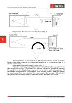
Automated system for tapes geometry measurement The principle of thickness measurement is shown in Fig. 2. The tape thickness is calculated as the difference between the position of shadow borders of the tape and the shaft. The position of shadow border of the shaft is controlled by a stand-alone micrometer. The structure of the control system is shown in Fig. 3. The system contains a group of 6 optical micrometers 1 for simultaneous control of the tape width and the group of 9 micrometers, 6 of them are intended for simultaneous control of the tape thickness and 3 (subsidiary micrometers) –...
Open the catalog to page 4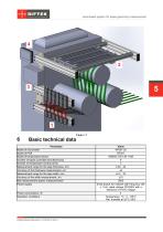
Automated system for tapes geometry measurement Basic technical data Parameter Model of micrometer Model of PDA Model of temperature sensor Number of tapes controlled simultaneously Number of temperature control points Measurement range for the tape thickness, mm Accuracy of the thickness measurement, um Measurement range for the tape width, mm Accuracy of the width measurement, um Max measurement speed, measurement/s Power supply Power consumption, W Operation conditions Value RF651-25 RF307 OMEGA OS-136-1-MA 6 3 0.02…20 ±5 ±0.2…20 ±10 2000 three-phase AC network with frequency (50 ± 1) Hz,...
Open the catalog to page 5
Automated system for tapes geometry measurement Overall and mounting dimensions Measurement modules Fig. 5 and 6 show the dimensions of measurement modules as well as their installation on equipment.
Open the catalog to page 6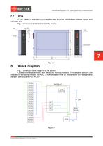
Automated system for tapes geometry measurement RF307 device is intended to process the data from the micrometers indicate results and store the data. Fig. 6 shows overall dimensions of the device. Block diagram Fig. 7 shows the block diagram of the system. Optical micrometers RF651 are linked via RS485 interface. Temperature sensors are included in the same network via ADC. The information from all micrometers and temperature sensors comes to the PDA RF307.
Open the catalog to page 7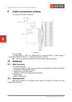
Automated system for tapes geometry measurement Cable connections scheme Fig. 8 shows the cable connections. Fig. 8 indicates: 1– power supply, 2 – PDA, 3,6 – RS485 cable, 4 – switching center, 5 – power supply, 7 – micrometers RF651 (15 items), 8 – temperature sensors (3 items). (!) The power should be switched off while mounting cable connections. Main functions The software provides: · receipt and analysis of data from micrometers and temperature sensors with display and storage of measurement results; · indication out of the valid values; · calibration of thickness measurement subsystem;...
Open the catalog to page 8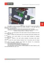
Automated system for tapes geometry measurement Press Start to initiate the measurement process. The results of measuring the width of strips are shown in the upper left part of the window, thickness – in the upper right and temperature – in the central part. The width of the tape is the result of direct measurement of the micrometer. The thickness of the tape - the result of indirect measurements, calculated as follows: Thickness=(Tape_sp-Shaft_cl) - (Shaft_sp - Shaft_cl), where Tape_sp – the current position of the upper surface of the tape (indicated by the main micrometers, see p. 5), Shaft_cl...
Open the catalog to page 9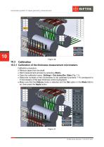
Automated system for tapes geometry measurement 10.3.1 Calibration of the thickness measurement micrometers Calibration procedure: · Remove tapes from the shaft. · Start measurement process by pressing «Start». · Open the calibration menu: Settings > Set etalon/Sw. State (Fig. 11). · Select the numbers of the micrometers to be calibrated (numbers 7-15 correspond to 9 micrometers of the tape thickness control subsystem). · Make sure that the Etalons mode is selected and the Set option in the Mode field is on, then press the Apply button.
Open the catalog to page 10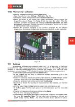
Automated system for tapes geometry measurement Stop the calibration process by pressing Stop button. Open the calibration menu Settings > Calibration (Fig. 12). Choose the number of temperature sensor (Sensor index field). Direct the sensor to the surface with stated temperature, having entered the temperature value in Temp. 1 or Temp. 2 field and press Set button. When the operation is finished successfully the message Calibration parameter has been successfully set appears. Detailed information on temperature sensors can be found in OMEGA OS136-1-MA documentation. · Perform the operation described...
Open the catalog to page 11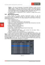
Automated system for tapes geometry measurement Etalons – the mode of setup/reset of micrometers calibration is active. Use the States function to disable the devices that are not used in the polling during the system operation. It is necessary when the device is faulty or is not in use, neglecting the recommendation above may cause long delays while polling and therefore the entire system delay. The use of the Etalons mode is described in p. 10.3.1. · To set the number of measurements used to calculate an average value use the Averaging field. Measurement journal During operation the system...
Open the catalog to page 12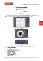
Automated system for tapes geometry measurement NOTE. To enter the date and time values are special graphics components shown in Figures 15 and 16, respectively. To enter numeric values use keypad, Figure 17. When typing the corresponding values the keyboard appears automatically. Prepatation for use Preparation of the system includes: · external inspection; · set up on a conveyer; · switching the system; · calibrating the system; · system setup.
Open the catalog to page 13All RIFTEK EUROPE catalogs and technical brochures
 PRODUCT CATALOG 2025
44 Pages
 RF603 Series Manual
49 Pages
 RF602 Series Manual
33 Pages
 RF603HS Series Manual
36 Pages
 RF609 (RF609Rt) Series Manual
33 Pages
 RF600 Series Manual
46 Pages
 RF605 Series Manual
29 Pages
 RF60i Series Manual
46 Pages
 RF62x Manual
174 Pages
 RF25x Series Manual
34 Pages
 RF651 Series Manual
32 Pages
 RF656 Series Manual
32 Pages
 RF656XY Series Manual
33 Pages
 Laser probes Manual
14 Pages
 Pipe ID Control System Manual
18 Pages
 Edge Sensor RF659 Series Manual
25 Pages
 RF627Smart-Weld manual
103 Pages
 PRODUCT CATALOG 2024
40 Pages


- Measuring device
- RIFTEK measuring system
- Windows software
- Industrial software
- Measurement software
- Position transducer
- Sorting machine
- Linear position transmitter
- Digital gauge
- Displacement transducer
- Linear displacement sensor
- Automatic sorting system
- RIFTEK automatic measuring system
- RIFTEK optical measuring system
- Inspection machine
- No-contact position sensor
- High-precision measurement system
- Linear encoder
- RIFTEK 3D scanner