- Catalogs
- Riels Instruments
- FLU Paddle Flow Switches Riels® Instruments
FLU Paddle Flow Switches Riels® Instruments
1 /4Pages

FLU Paddle Flow Switches Riels® Instruments
1 /4Pages
Catalog excerpts

PADDLE FLOW SWITCHES FLOW CONTROLS Magnetic Paddle Flow Switch The Riels magnetic flow switches are the most used devices in most industrial applications, for on / off control of the gas and liquid flow. To get executions that meet the main environmental and safety requirements, the paddle flow switches can be built in variants with SPDT or DPDT micro-switch electrical contacts and they can mount different custody models which include an optional version with dual color visual flow indicator. Available Versions Flu A for the gas flow control Flu O for checking the flow of liquids All data and contents of this sheet are the exclusive property of Riels Instruments Applications - Protection of pumps, motors and other equipment from the adverse effects given by a low or absent load. - Checking function of sequentially placed pumps. - Automatic activation of pumps and / or auxiliary engines. - Interruption of engines, systems and process systems operating with liquid cooling, in the case of the coolant flow block. - The burner block to the occurrence of a fault to the passage of the air flow through the heating coil. Approximate implementation/Unimplementation of flow for cold water (m3 / h) Flu O model with two-color visual flow indicator and waterproof housing Approximate implementation/Unimplementation of speed for cold water (m3 / h) Available Models Two oscillating magnets placed on the same axis (the first integrated in the paddle and the second integrated in the electric equipment) repel each other via a non-magnetic material flange. The flange separates the housing, which contains the electrical equipment, from the paddle inserted in the pipe. In the absence of flow, the paddle is kept in its rest position by the action of balancing and repulsion of the two magnets placed opposite each other, having the same polarity. When the flow pushes the paddle, the magnet integrated in it is set in motion, and the magnetic field pushes the integrated magnetized switch. The switching of the electrical contact is fast and reliable. Mounting Riels FLU Flow switches can be installed horizontally, directly in the pipeline, or in a specific room connected between two pipes. For this purpose, various types of unit adapter flange to the requirements of specific applications are available. For the control of the gas flow, with IP67 aluminum housing To control the flow of liquids, with IP67 aluminum housing and two-color visual indicator of flow (on request). Contact Parts FLANGE Steel
Open the catalog to page 1
Process connections Different solutions are possible, adapted to the diameter of the pipe and used with custom paddle arms. All data and contents of this sheet are the exclusive property of Riels Instruments Note: can be supplied, according to specific needs, many flange models. Design limit conditions TMA - Maximum allowable temperature PMA - Maximum allowable pressure Steel Steel -20 ÷ + 150 ° C ; up to 350 ° C with cooling extension < 16 bar g Note: on request, are available for pressure flanges> 16 bar g Flu O model with two-color visual indicator.
Open the catalog to page 2
Electrical equipment and enclosures for FLU paddle flow switches The electrical equipment of the Riels FLU flow switches is constituted by a support and a contact. The oscillating element includes a magnet, whose south pole pointing towards the flange which separates the electrical equipment from the gas and / or from the liquid passing in the pipe. In function of the pressure exerted on the paddle from the liquid / gas while it flows through the unit, the paddle acts by rotating a watertight cartridge that contains a magnet that has the south polarity on the end towards the flange. Since the...
Open the catalog to page 3
Guide to the correct selection and unit order Each device is identified by a unique alphanumeric code that defines the design features that best fit the application. Before you begin to configure the unit, you must check the following information. • • • • • • • Process pressure Design pressure Type of fluid Specific weight of the fluid Fluid viscosity Process temperature Design temperature Dimensions (approximate in mm) Order Codes Riels Model Tipe All data and contents of this sheet are the exclusive property of Riels Instruments Electrical connections DN (only for FO and FOT types) Flage material...
Open the catalog to page 4All Riels Instruments catalogs and technical brochures
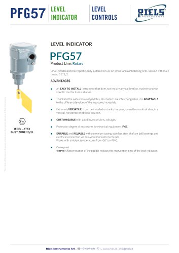 PFG57 LEVEL INDICATOR
2 Pages
 DEEPER
1 Page
 RIV110 Flow switch
2 Pages
 miniELCOR
4 Pages
 EL-USB-4
5 Pages
 EE33
EE336 Pages
 EE300Ex-HT
6 Pages
 Temperature Sensors
64 Pages
 AVFM 5.0
3 Pages
 EE 75
EE 755 Pages
 EE776
EE7766 Pages
 EE771/2
6 Pages
 TRICOR
15 Pages
 SE 404 X SE 406 X
2 Pages
 FFU
FFU7 Pages
 RIF600W
4 Pages
 RIF180
3 Pages
 MC 505
1 Page
 HM-R
HM-R3 Pages
 HD408T
2 Pages
 RIB300
3 Pages
 23/25 ED
2 Pages
 RIB180
4 Pages
 FLD48
FLD482 Pages
 CLM-36
6 Pages
 DLM-35
2 Pages
 DLS-27
7 Pages
 CLS-23
5 Pages
 PFG05/ATFHV60
2 Pages
 LFP
LFP2 Pages
 GRLM70
9 Pages
 RIL600
5 Pages
 LITTLE EX
1 Page
 MATIC/V/MC
2 Pages
 DCX22
DCX222 Pages
 RIV165 Paddle Flow Switches
2 Pages
 RIV170 Paddle Flow Switch
2 Pages
 RIV150 Flow switch
2 Pages
 Riels® Instruments Catalog
24 Pages
 MN03
MN031 Page
 LEO RECORD
2 Pages
 EV220B
13 Pages
 WWG
WWG1 Page
 FAM_Air_flowmeter_riels
1 Page


- Valve
- Control valve
- Flowmeter
- Stainless valve
- Ball valve
- Temperature probe
- Volume flow monitor
- Pneumatic valve
- Liquid flow monitor
- Force sensor
- Electrically operated valve
- Regulating valve
- Gas analyzer
- Concentration analyzer
- Data logger
- Gas solenoid valve
- Resistance temperature sensor
- Electric valve
- Pressure transmitter
- Liquids analyzer