- Catalogs
- Ridart srl
- 60 GH angle check valve

- Company
- Products
- Catalogs
- News & Trends
- Exhibitions
60 GH angle check valve

60 GH angle check valve
- Material: Cast iron with options for PTFE coating.
- Components: Body (Cast Iron/PTFE), O-Ring/Seal (Viton®/PTFE), Poppet (Brass/Stainless Steel), Cap Material (Brass/PTFE Coating).
- Temperature Range: -20°C to +60°C.
- Pressure: Max working pressure of 16 PN.
- Various sizes and codes are available, ranging from 110 mm to 235 mm in diameter.
- Install at the highest point of the tank, typically on the manhole cover.
- Follow directives and user manual for correct installation.
- Periodic checks are necessary to remove dirt.
- Replace after fire or deflagration; tampering voids warranty and safety.
- Standard model is for traditional fuel without additives.
- PTFE coated model available for special fuels and compatible chemicals.
- Product certification, declaration of conformity, user manual, and testing information available at www.ridart.it/support.
Catalog excerpts
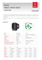
60 GH ANGLE CHECK VALVE Cast Iron This angle check valve is designed to prevent the drainage of fuel (loss of prime) in the suc on line and permits the product flowing only towards a dispenser. The valve is installed on the manhole lid of the storage tank. The cast iron angle check valve is a device according with Direc ve 2014/34/EU and harmonized standard. CAST IRON CAST IRON+ PTFE COATING STAINLESS STEEL BRASS+ PTFE COATING
Open the catalog to page 1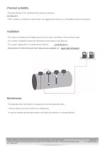
Chemical Suitability - Standard Model is for tradi onal fuel without addi ves. ON REQUEST: - PTFE coated is a model for special fuel, non-aggressive solvents or compa ble chemical products. Installa on - The valve is installed at the highest point of the tank, normally on the manhole cover. - For correct installa on follow the Direc ves and product User Manual. - For custom applica on or maintenance write to: - Declara on of Conformity and User Manual are available on: www.ridart.it/support Maintenance - Periodically check the device is necessary to remove possible dirty. - Always replace the...
Open the catalog to page 2All Ridart srl catalogs and technical brochures
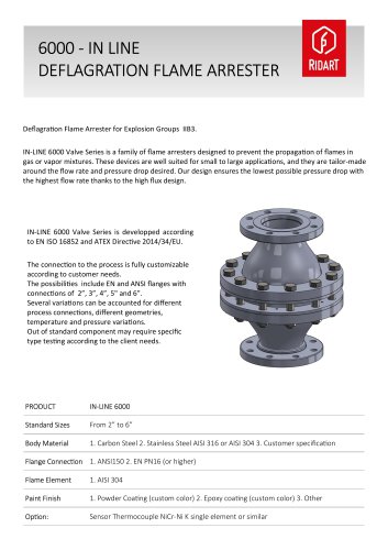 Ridart 6000
3 Pages
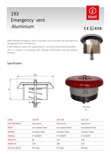 193 emergency valve
2 Pages
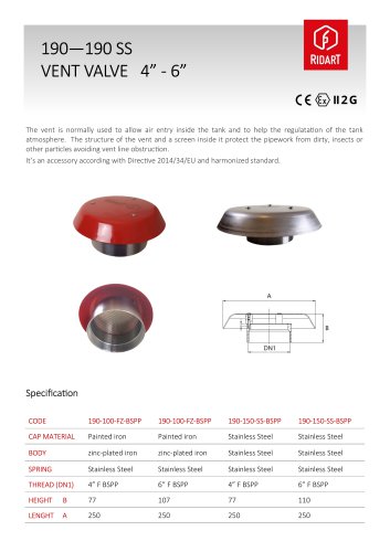 190 vent dn100 - dn150
2 Pages
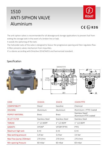 1510 ANTI-SIPHON VALVE
2 Pages
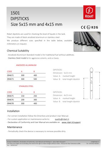 1501 dipstick for tank
1 Page
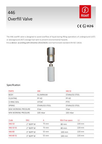 446 OVERFILL VALVE 2" - 3"
3 Pages
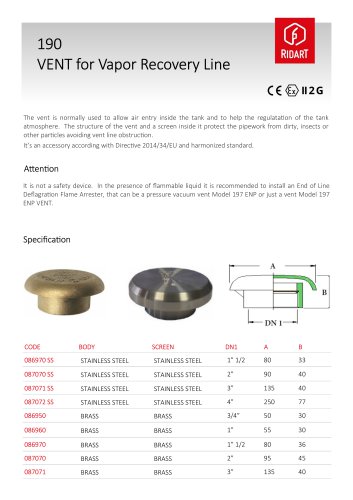 190 VENT CAP
2 Pages
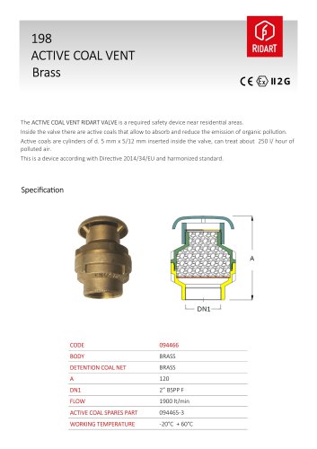 198 active coal vent
2 Pages
 197B3 PRESSURE/VACUUM VALVE
2 Pages
 62 angle check valve
2 Pages
 1521 FEMALE API COUPLER
2 Pages
 93 VAPOR STOP 3" /4"
3 Pages
 in line flame arrester
5 Pages
 overfill prevention valves
4 Pages
 RIDART CATALOG
39 Pages