- Catalogs
- RICHMAN UNIVERSAL SOURCING CO LIMITED
- RV series aluminum worm reducer
RV series aluminum worm reducer
1 /28Pages

RV series aluminum worm reducer
1 /28Pages
Catalog excerpts

Product explanation Technical charts symbols Guide for Choosing & User Manual A. Notices for type-choosing B. Notices for installation and usage C. Maintenance notices Guide for type-choosing & Radiaal loads Solution and reason for the general faults of variator Motor coefficient tables The motor in common use as follow RV.VF series Catalog RV Series worm-gear speed reduces VF Series worm-gear speed reduces "Qiangzhu"brief Introduction of products 2) 3) KSMsfcMiS. ttfStta, STStf'fttti 4) ftMtk*. )m±, 5) iitTTfl. Iftlf'N 6) sffltta. \% M 5'J r p°p 5'J A2001 ^ JM S £ft & Tr £ $10* n°o . 2002^it r wxr i. Product explanation DHtneiflBfl Technical charts symbols Gearbox with solid input shaft RV. VF Series Worm gear speed reducers is designed and manufactured according to Q/Z J1-2000 technical quality standard. These series are in compliant with the national standard GB10085-88 cylinder worm turbo parameter and combined with the most advanced technology inside and outside China to design and make Square Chest Wall. This machine with thin wall pattern radiator and design via static structure is cast by compression with high-quality aluminum alloy, which has the advances and features as follows: 1) Compact structure, light size, small and high efficiency. 2) Good function of heat exchange, rapid heat rejection. 3) Easy installation and flexible connecting style. Easy for maintaining and checking. 4) Large in both transmission ratio and twisting distance (N.m) resulting to high capacity of bearing and loading. 5) Stable operation, little noise, long lasting. 6) Widely applicable and liable. These series are listed in important R&D products in China in 2001 and in Guangdong in 2002. The products are widely applied in the producing equipments of all kinds of industries inside and outside China. They are the best choices for nowadays modern facilities of mechanical reducing drive control to realize large twisting distance, large gear ratio, little noise, high efficiency and stability. RV..FA.. PC+RV RVE..FA.. $ i fctn motor mounting flange Configuration size consult the page
Open the catalog to page 1
fciltk nmmn £MS§}Affl*§ ffixmm mmmm gmmmmxim i£A&fflS£^ (*) SUAjAifc^i (CW-CCW)(**) itA£iZfflS£ig(*) (CW-CCw) (**) Calculated thrust load at gearbox input shaft Calculated thrust load at gearbox output shaft Rated thrust load at gearbox input shaft Rated thrust load at gearbox output shaft Reduction ratio Acceleration factor of masses Radial load stress factor Rated brake torque Transmitted torque at gearbox input Transmitted torque at gearbox output Calculated torque at gearbox output Gearbox rated output torque Required torque at gearbox output Angular speed at gearbox input Angular speed at...
Open the catalog to page 2
Radial loads Pl=Px Kl K2 M2=Mx Kl K2 Pl=Px-Kl K2 M2=Mx K1K2 p*-T_mm is w ijj w- (k w): Pi—®.*JlM(kW); Ki idlin' m a M3, Mx - Twisting Distance (N.m) for working machine P* - Power (kW) for working machine M2- Twisting Distance (N.m) for reducer output Pi - Power (kW) for electric machine Ki - Oilbath lubricating factor of reducer as the Table 3 K2 - Working amendment factor of reducer as the Table 4 ^3: Table3: Oilbath lubricating factor of reducer (Ki) ;± : ^JTi^;mJ$^3O'-4OJC0Tf, JiZfll.1 ~1.2 j Notice: II should multiply the working amendment factor 1.1 1.2 on the temperature of 30~40yC. (.mt...
Open the catalog to page 3
3? aiiwis?^g«i^ Motor coefficient tables !S Bi Is HI E? B5 )K U]\ }2i Solution and reason for the general faults of variator Fault description Note:lf occurrence other the breakdown can't solue.please at any time with we comtact,for the purpose of offering consnct the service. ;i: 4®Htl^^fe^]t/l(5]^^iil500r/min. 380V. 50HZ 6iKH*l^fe^mi5]'£$fii1000r/min. 380V. 50HZ 56-132 #US*fB££*|'36: Note:4P 3-Phase driving induction motor rotation synchronization speed is 1500rmin.380V.50HZ. 6P 3-Phase driving induction motor rotation synchronization speed is 1000rmin.380V.50HZ. 56-132 are aluminum alloy boxs;...
Open the catalog to page 4
RV Series Catalog! RV S IS B14 Mounting position Frame size RV series worm gear speed reducers Product structure Code for type Demonstration RV series mounting positions PC+RV series mounting positions RVE series mounting positions Mounting positions of output flange Positions of Motor junction box Table 8: Lubrication oil Chosen Table 9: Adding Capacity of lubrication Oil PC+RVCombinations Design features ( PC ) Coupling to electric motor Output cover Torsion arm PC+RV Dimensions/RVE Dimensions RV Coefficient tables RV Gearbox dimensions Rv&mmtmmmu RV series worm gear speed reducers *%/ Type...
Open the catalog to page 5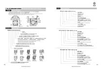
RV Series worm-gear speed reduces 1.(RV025~ RV063 are aluminum alloy boxs. RV075- RV090 have aluminum alloy boxs or cast iron boxs RV110- RV150 are cast iron boxs.) 2. Two sides of worm RV025-RV063 are deep-channel ball bearing,RV075 above are conic roller bearing. bol for Installation type. - &fflZA$fiiij;£^& ZA for output flange. ------ DZ for single-shaft output. -----------------$ftAfe3MAtt^A0.75KW Motor power (0.75KW). FA indicates flange input. --P80S«lffiWB5HfA;i^(#j»A^llti49i) Motor size(P80),input flange(B5)(only for input flange). -------i£tb30 ominal speed ratio 30 of worm-gear speed...
Open the catalog to page 6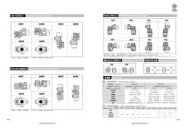
RV SZ ?i Ri it RV series mounting positions RVESiiHJS RVE series mounting positions AD;S?L • llb'fiti 0 Oil inlet a Oil gage • Oil drainage plug — 2 ^ Mounting positions of output flange §f*nt§||15B Positions of Motor junction box PC+RV it PC+RV series mounting positions
Open the catalog to page 7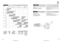
PC+RV Combinations f Design features(PC) PC (fl&) 0t)^p°, Silt'S The PC construction is modular and therefore it can be supplied as a separate unit to be mounted on any type of fitted geared motor (PAM). In this connection, the various possibilities of flange/output shafts can be found on page 050 to 056. Fitting the pre-stage helical module on the main reduction unit is easily done as for any motor of type B14. The pre-stage unit cannot be used by itself, but only coupled with another reduction unit. Coupling to electric motor PC unit connects with motor by hole-shaft design, easy mounting but...
Open the catalog to page 8All RICHMAN UNIVERSAL SOURCING CO LIMITED catalogs and technical brochures
 K series helical gearbox catalog
118 Pages
 F series gearbox
84 Pages
 R series geared motor
110 Pages
 gear motor catalog
38 Pages


- Electric gearmotor
- Coaxial gearhead
- Precision gearhead
- Right angle gearhead
- Gear train gear reducer
- Hollow-shaft gearhead
- Transmission gearhead
- Right angle electric gearmotor
- Industrial electric gearmotor
- Multi-stage gearhead
- Shaft gearhead
- AC gear-motor
- Helical gear gearhead
- Gear train gearmotor
- Dual-stage gearbox
- High-performance gearhead
- Low-noise gearhead
- Low-backlash gearhead
- Clamp gearbox
- High-precision gearhead