

PSU-20

PSU-20
- ON/OFF control via AC/DC switch.
- Visual indicators for AC power, DC power, and battery charge status with color-coded lamps (red for AC, orange for DC, green for recharge).
- Exposure type form with a powdered coating case.
- Dimensions: 300 x 400 x 180 mm.
- Input Voltage: AC220V, 60Hz.
- Output Voltage: DC24V.
- Power Consumption: 125W.
- Output Capacity: 90W (DC24V, 5.2A).
- Secondary Power Supply: DC24V, 7AH maintenance-free lead-acid battery.
- Preparation Time: 30 mins (DC24V, 3.8A).
- Charging Time: Approximately 12 hours.
- Supports up to 20 detectors (0.18A per detector).
- Ensure AC-DC power and signals are blocked during installation and maintenance.
- Avoid moisture penetration and reverse battery connection.
- Disconnect battery connector when not in use to prevent over-discharge.
- AC Power Error: Check AC supply and fuse.
- DC Power Error: Check AC power, DC fuse, and terminal connections.
- Auto Charging Problem: Verify connector connections and voltage levels.
Catalog excerpts

Advanced Sensor & Optics Power Supply Unit for flame detector Model : P S U - 20 〔Features〕 PSU-20, a power supply device is for facilities which need DC24V output rectified from AC220V input and secondary power supply at electric power interruption. ■ Function ・ ON / OFF control by AC, DC Switch ・ Visual display on AC power, DC power, battery charge status color Lamp operation recharge ■ green Regular blinking : on recharge ■ Design Item Form Case Dimension Description Exposure type Powdered coating 300 x 400 x 180 (mm) Input Voltage Output Voltage Power Consumption Output Capacity Capacity for Secondary Power Supply Preparation Time Charging Time No. of detectors to be connected (as of 180mA per detector) battery 30 mins. ( DC24V, 3.8A ) about 12 hours 0.18A × 20(detectors) ≒ 3.6 A < 3.8 A Tel: +82-31-348-4247 Fax: +82-31-420-0800 E-mail : [email protected] Web-site
Open the catalog to page 1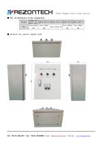
Power Supply Unit for flame detector ■ No. of detectors to be connected Model No. ■ pictures for power supply unit Tel: +82-31-348-4247 Fax: +82-31-420-0800 E-mail : [email protected] Web-site : www.rezontech.co
Open the catalog to page 2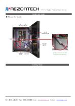
Power Supply Unit for flame detector [inside and notes] ■ Picture for inside AC/DC REOHARGING LAMP VOLTAGE METER TERMINAL BLOOK [ Battery connector connection] Handling Notes 1. For installation and maintenance, you must block AC-DC power and all the related signals and take safety outfits. 2. DC short could cause error on internal PCB. Please take care. 3. Make sure that moist does not penetrate into electronic equipment. 4. When not using power supply casing, disconnect the battery connector against over-discharge. 5. Avoid reverse connection on a battery. (A buzzar rings at reverse connection.)...
Open the catalog to page 3
Power Supply Unit for flame detector Fault diagnosis Contact us, Rezontech headquarter, for more for trouble shooting. ● AC power error Symptom a. AC lamp does not go on with AC switch 'On'. a. Make sure that AC 220V be supplied with to AC-L and AC-N terminals. b. Check with AC fuse. ● DC power error Symptom a. DC lamp does not go on with DC switch 'On' a. Check any AC power error. b. Check with DC fuse. c. Check +. - connection on terminal lug. d. For overcurrent from short or line leaks, block DC switch and remove loads on the (Protection circuit operating could block power supply for several...
Open the catalog to page 4
Power Supply Unit for flame detector Wiring Diagram ■ Wiring Diagram(alternating current power supply, receiver, detector) power for flame detector CN4-1 ■ Wiring Diagram for power supply unit Tel: +82-31-348-4247 Fax: +82-31-420-0800 E-mail : [email protected] Web-site : www.rezontech.co
Open the catalog to page 5All REZONTECH catalogs and technical brochures
 FIRE Detector RMD-5T
2 Pages
 Eagle Flame Detector Series
4 Pages
 Condensed Fire Aerosol
7 Pages


Archived catalogs
 REZONTECH FLAME DETECTOR
8 Pages
 2018 Rezontech Catalog
4 Pages

- DC power supply
- AC/DC power supply
- Portable tester
- Gas detector
- Industrial tester
- Industrial detector
- Metal stand
- Infrared detector
- Detector with alarm
- Carbon monoxide detector
- Oxygen detector
- Analog detector
- Explosion-proof detector
- Electrochemical detector
- Real-time detector
- Toxic gas detector
- Hydrogen sulfide detector
- Methane detector
- Adjustable stand