
- Catalogs
- Rexnord Industries, LLC
- Rexnord® and Link-Belt® Engineered Steel Chains Catalog


Rexnord® and Link-Belt® Engineered Steel Chains Catalog

Rexnord® and Link-Belt® Engineered Steel Chains Catalog
Rexnord has been a leader in providing high-quality, engineered products for over 100 years, focusing on improving productivity and efficiency in industrial applications. The company is committed to exceeding customer expectations in product design, application engineering, operations, and customer service. Rexnord offers a comprehensive portfolio of power transmission and conveying components worldwide.
Rexnord provides customer service across various regions including Australia, Brazil, Canada, China, Europe, Latin America, Mexico, Singapore, and the United States. Contact details for each region are provided for customer support.
Chain life is critical in selecting a chain supplier. Rexnord emphasizes wear resistance and fatigue strength as key factors in chain durability. The company uses superior materials and heat treatment processes to ensure long-lasting chain performance. Rexnord's chains are pre-lubricated and shrink-wrapped to prevent corrosion and wear.
Rexnord offers specialized chains for various applications including high-performance elevator chains, grain handling chains, amusement rides, in-floor conveying, steel industry, reclaimer and barge unloading, bottling and beverage industry, sugar processing, food processing, and distribution and material handling. Each application has specific chain types and configurations to meet industry needs.
The document includes detailed technical data on chain design, selection, maintenance, and engineering. It provides insights into the manufacturing processes and quality control measures that ensure the reliability and performance of Rexnord chains.
Rexnord's commitment to quality and customer service is evident in its extensive product offerings and global support network. The company's expertise in engineered chains makes it a trusted partner for industrial applications worldwide.
The document discusses the design and heat treatment processes used by Rexnord to enhance the strength and wear life of their welded steel chains. The focus is on providing superior value and productivity through advanced manufacturing techniques.
Rexnord employs advanced heat treatment technologies to improve the hardness and toughness of chain components. This includes the use of computer-controlled furnaces and induction heat treating equipment. The process ensures that the chains have the hardest possible wearing surfaces while maintaining the necessary toughness to resist shock loads. The Selectively Induction Hardened (SIH) process is highlighted, which hardens only the parts of the chain that wear, ensuring durability without compromising toughness.
The document emphasizes the importance of heat treatment in extending chain wear life. By increasing the hardness of components, the wear life of chains can be significantly extended. For example, increasing hardness from 35RC to 60RC can potentially double the chain life. Rexnord's chains come standard with premium heat treatments, which are crucial for consistent wear life and predictive maintenance.
Rexnord chains are designed with superior fatigue strength due to tightly controlled interference fits between the pin and sidebar hole. This design increases the fatigue life of the chain and prevents unexpected failures. The document contrasts this with competitive chains that have poorly controlled fits, leading to lower fatigue strength.
The document details various series of Rexnord chains, including the Narrow Series (WH, WHX, WSX) and Wide Series (WDH). Each series is designed for specific applications, with options for different materials and configurations. The chains are available with features like thru-hardened parts, selectively induction hardened rivets, and stainless steel construction.
Rexnord has developed a reverse barrel design to address wear issues caused by scrubbing between the chain barrel and sprocket tooth. By reversing the barrel, the articulation occurs inside the chain joint, reducing wear and extending the life of the chain and sprocket.
These chains are designed for severe abrasion and heat conditions. They feature hardface welding on sliding surfaces, interference fits for improved strength, and induction hardened pins for longer service life. The design also includes square edges for efficient material conveyance.
Rexnord's welded steel chains are engineered for maximum strength and wear life through advanced heat treatment and design processes. The document highlights the company's commitment to quality and innovation in chain manufacturing.
- Surfaces must be clean and free of foreign material before welding.
- Weld strength should cause failure in the parent metal, not the weld.
- Welds should be free of defects like cracks and slag.
- Convex weld beads are preferred for strength.
- Electrode E7018 is recommended, and electrodes should be stored dry.
- Preheating to 300°F and postheating to 700°F are beneficial for large attachments.
- Avoid welding on induction hardened or carburized parts to prevent tempering and brittle welds.
Sprockets are essential components in chain-driven systems, available in various materials and styles to suit different applications. Fabricated steel sprockets are recommended for most engineered chain applications due to their performance, availability, and cost-effectiveness. Cast sprockets are also available, with or without hardened teeth, and are designed for optimal chain-sprocket interaction.
- Cast Arm Body: Used for larger sizes, reducing weight and cost.
- Cast Split Body: Facilitates easy mounting and removal without disturbing other equipment.
- Cast Plate Body: Suitable for smaller sizes or when chain pull exceeds arm body strength.
- Fabricated Steel Sprockets: Made from carbon steel with hardened teeth.
- Shear Pin Sprockets: Include shear pins to prevent damage during overloads.
- Special Sprockets: Custom designs for specific industries.
These can have solid or split bodies with replaceable segments or rims, made from hardened steel for wear resistance. They are ideal for abrasive environments and can double sprocket life by reversing segments.
Fabricated steel sprockets typically have induction-hardened teeth. Segmental sprockets undergo a carburizing and induction heat treatment process for increased hardness and durability.
- Number of Teeth: Minimum of 12 teeth recommended for high speeds and loads.
- Height of Teeth: Designed to accommodate wear elongation and clear chain attachments.
- Bore and Hub Size: Determined by the torque to be transmitted, with standard specifications provided.
- Gapped Sprockets: Used to avoid interference with chain attachments.
When ordering sprockets, specify quantity, unit number, chain number, number of teeth, material, heat treatment, hub construction and size, bore size, keyseat, setscrews, and any special requirements. Fabricated steel sprockets are recommended for quick delivery.
- Multiple Sprocket Alignment: Ensure proper alignment for multiple strand conveyors.
- Web Holes: Available for large sprockets for hoisting purposes.
- Weights: Provided for estimating shaft loads and freight charges.
- Hubs: Available in various styles, with standard long central hubs unless specified otherwise.
- Plate Thickness: Lists thickness for each sprocket unit, essential for determining the proper unit number for each chain.
- Fabricated Steel Sprockets: Available in various sizes and configurations, including wide mill chain sprockets and traction wheel assemblies.
- Hub Specifications: Detailed dimensions for bore sizes, maximum torque, hub diameter, length, and weight are provided for different hub letters (A to Z).
- Using Tables: Instructions on how to use tables to determine recommended bore and hub sizes based on torque and shaft material limitations.
- Calculating Sprocket Weight: Formula provided to estimate total sprocket weight for shaft load and shipping weight calculations.
- Material and Construction: Sprockets are available in fabricated steel, with recommendations for using fabricated steel over cast for improved performance.
- Hub Lengths: Minimum recommended lengths are provided, with options for longer hubs at additional cost.
- Octagonal Tail Wheels: Advantages over conventional sprockets include direct force transmission and reduced wear.
- Hub Dimensions: Tables provide dimensions for solid and split hubs, including bore sizes, torque capacities, and weight.
- Sprocket Dimensions: Detailed tables for sprocket pitch diameter, tooth width, and weight for various chain numbers.
- Key Sizes: Information on key sizes for different bore diameters and hub sizes.
- Torque and Bore Intersections: Guidelines for selecting appropriate hub diameters and lengths based on torque and bore size intersections.
- Design Shear Stress: Maximum torsional shear stress for typical shaft material is 6,000 psi.
- Certified Dimensions: Dimensions are subject to change, and certified dimensions are available upon request.
The document provides detailed specifications for various components such as body bolting, sprockets, and buckets. Torque values are based on dry conditions, with 1 Ft. Lb. Torque equating to 1 Lb. Force with a 1 Ft. Lever Arm. Dimensions for sprockets and buckets are subject to change, and certified dimensions are available upon request.
Instructions are provided for the installation and maintenance of segmental sprocket rims and traction wheels. These components are designed for easy installation and replacement without the need to remove the chain or perform cutting. The document emphasizes the importance of proper chain-sprocket interaction and provides guidelines for selecting the appropriate chain and sprocket combinations.
The document outlines the standards for chain ratings, emphasizing the importance of selecting chains based on working load and speed limitations. It also highlights the importance of considering factors such as fatigue strength, wear capacity, and environmental conditions when selecting chains.
Comprehensive selection procedures for drive, conveyor, and elevator chains are provided. The document includes guidelines for determining horsepower, service factors, and design horsepower. It also offers advice on selecting the most economical chain and sprocket combinations based on factors such as cost, space limitations, and availability.
The document includes tables with torque values, sprocket dimensions, and chain selection criteria. Figures illustrate various drive arrangements and the relative positions of sprockets, highlighting the best and least recommended configurations for optimal performance.
- Chain Selection: The 3100 Series chains can replace ANSI roller chains up to 350 RPM and operate over the same sprockets. Larger pitch chains are recommended for larger driver shaft sizes.
- Noise Considerations: Smaller pitch chains on cut tooth sprockets provide quieter operation.
- Sprocket Selection: Alternatives to the 12-tooth sprocket include 9-tooth and 15-tooth options, each with specific advantages and limitations.
- Determine Horsepower: Calculate based on motor or engine specifications.
- Service Factor: Use tables to determine the appropriate service factor based on application and operating hours.
- Design Horsepower: Multiply actual horsepower by the service factor.
- Speed and Shaft Size: Consider the RPM and diameter of both driver and driven shafts.
- Drive Chain and Sprocket: Select based on design horsepower and RPM.
- Space and Speed Ratio: Ensure sprocket and chain fit within available space and calculate speed ratio.
- Center Distance and Chain Length: Calculate using provided formulas and tables.
- Sprocket Material and Hub Selection: Choose based on torque requirements and material availability.
- Lubrication: Follow recommended methods and lubricants for optimal performance.
- Use fabricated steel sprockets with induction hardened teeth for drive applications.
- For smooth operation, use sprockets with as many teeth as possible to minimize chordal action.
- Chordal Action: Speed variation decreases with more teeth in the sprocket, becoming negligible with 21 or more teeth.
- Service Factors: Adjust based on application type and operating hours, with specific factors for motor and engine-driven applications.
Service Factors:
The document provides a detailed table of service factors for various industrial applications, which are essential for determining the appropriate design and selection of mechanical components. Service factors are adjusted based on the type of prime mover and the duration of operation. For example, a uniformly loaded belt conveyor operating for 10 hours a day has a service factor of 1.00. However, if engine-driven for the same duration, the factor increases to 1.2. For intermittent operations, the factors vary further.
In environments that are extremely wet or abrasive, an additional 0.25 should be added to the service factor to account for increased wear and tear.
The document references AGMA (American Gear Manufacturers Association) standards for gearmotors, indicating that the service factors listed are minimum values under normal conditions. For specific applications or conditions not covered, consultation with Rexnord is recommended.
The document includes tables for selecting drive chains, specifying the number of teeth on driver sprockets, and the largest keyseat bore. It emphasizes the importance of using fabricated steel sprockets and provides guidelines for manual lubrication.
Overall, the document serves as a comprehensive guide for selecting appropriate service factors and mechanical components based on application type, operational conditions, and environmental factors. It highlights the importance of adhering to industry standards and consulting with manufacturers for specific requirements.
This document provides detailed guidelines for the design and selection of conveyor chains, specifically for Class 3, 4, and 4A conveyors. It includes formulas, coefficients, and factors necessary for calculating chain pull, weight, and horsepower requirements.
- Chain Pull (Pm): Calculated using the formula Pm = W(Y – f1X), where W is the weight of moving conveyor parts, Y is the vertical rise, and f1 is the coefficient of friction.
- Weight Calculations: The weight of material handled per foot (M) and the weight of moving conveyor parts (W) are critical for determining the chain pull.
- Friction Coefficients: Various coefficients are provided for different materials and conditions, such as chain sliding on steel or wood, and material sliding on troughs.
- Design Working Load: Calculated by modifying the maximum chain pull (Pm) with service and speed factors.
- Speed Factors: Provided for different numbers of teeth on sprockets, affecting the design working load.
- Material Friction Factors: Tables are provided for different materials, indicating friction factors for sliding on steel troughs and side friction constants.
- Determine Conveyor Class: Based on the type of chain and material handling requirements.
- Estimate Total Chain Pull: Using the provided formulas and coefficients.
- Make Tentative Chain Selection: Consider wear life, cost, and operating conditions.
- Verify Chain Selection: Recalculate chain pull and design working load with exact chain and attachment weights.
- Environmental Conditions: Temperature and corrosive conditions affect chain selection.
- Attachment Links: Selection based on conveyor arrangement and available components.
The document emphasizes the importance of selecting the appropriate chain type and configuration based on specific operational requirements and environmental conditions. It provides comprehensive tables and formulas to aid in the accurate calculation of necessary parameters for efficient conveyor operation.
The document outlines the procedures for selecting conveyor chains, focusing on calculating the power required (Pm) and determining the design working load. The service factor is chosen based on uniform loading, with a factor of 1.2 for conveyors operating over 10 hours daily. A tentative chain selection is made using a chart, recommending an engineered steel roller type chain for Class 2 conveyors.
Horsepower (HP) is calculated using the formula: HP = 1.15 (S) (MDK + MY) / 33000, where various parameters like material weight, chain weight, and elevator speed are considered. The document provides detailed formulas for determining chain pull and design working load.
The chain pull (Pm) is calculated using specific formulas, considering factors like chain weight and friction. The design working load is then determined, ensuring it does not exceed the maximum recommended load.
The document lists essential data for selecting conveyor and elevator components, including equipment life, environmental conditions, sprocket details, and material characteristics.
Maintenance guidelines emphasize the importance of proper chain connection and disconnection, safety precautions, and the use of appropriate tools. It advises against altering standard press-fit chains and highlights the significance of lubrication for extending chain and sprocket life.
Proper sprocket design and maintenance are crucial for preventing premature chain failure. The document suggests methods to increase chain and sprocket life, such as reversing sprockets to utilize unworn tooth faces and ensuring smooth chain-sprocket interaction.
The document discusses the effects of temperature changes on materials, specifically focusing on linear expansion and stress changes. The change in length due to temperature is calculated using the formula εtl, where ε is the coefficient of linear expansion, t is the temperature change, and l is the length. For fixed ends, the change in unit stress is Eεt, with E being the modulus of elasticity and A the cross-sectional area.
1. A ferritic malleable iron piece, initially 40 inches at 60°F, expands to 40.007 inches at 90°F when ends are free.
2. For fixed ends, a 30°F increase results in a unit stress change of 5133 psi.
The document includes a table of coefficients of linear expansion for high temperatures, judged by color, and a detailed chain and sprocket index listing various chain types, pitches, and applications.
This section provides a comprehensive list of chains categorized by number, type, and application, including drive chains, elevator and conveyor chains, and welded steel chains. Each entry includes specifications such as pitch and sprocket compatibility.
The document concludes with a subject index covering topics like amusement ride applications, chain selection procedures, and engineering information, providing a guide to the document's contents.
- Chain Types and Specifications: The catalog covers different types of chains including bar drive chains, straight sidebar chains, welded steel chains, and elevator and conveyor chains. Each type is detailed with specifications and applications.
- Sprockets and Hubs: Information on various sprocket types such as cast, fabricated steel, and segmental rim sprockets is provided. The section also includes details on solid and split hub bodies.
- Selection Procedures: The document provides tables and guidelines for selecting the appropriate chains and sprockets based on application requirements, including service factors and system design considerations.
- Maintenance and Engineering: Guidelines for chain maintenance, lubrication, and heat treatment processes are included. Engineering constants and material strength comparisons are also provided.
- Special Applications: Chains for specific industries such as amusement rides, bottling, and food processing are discussed, highlighting their unique requirements.
- Customer Service: Contact information for Rexnord's global customer service centers is provided, emphasizing their commitment to quality and customer satisfaction.
Catalog excerpts

Rexnord® and Link-Belt® Engineered Steel Chains I Catalog Conveyor, Elevator & Drive Chains World Class Customer Service For more than 100 years, the dedicated people of Rexnord have delivered excellence in quality and service to our customers around the globe. Rexnord is a trusted name when it comes to providing skillfully engineered products that improve productivity and efficiency for industrial applications worldwide. We are committed to exceeding customer expectations in every area of our business: product design, application engineering, operations, and customer service. Because of our customer focus, we are able to thoroughly understand the needs of your business and have the resources available to work closely with you to reduce maintenance costs, eliminate redundant inventories and prevent equipment down time. Rexnord represents the most comprehensive portfolio of power transmission and conveying components in the world with the brands you know and trust. Rexnord and Link-Belt are registered trademarks of Rexnord Industries, LLC. All rights reserved. WORLDWIDE CUSTOMER SERVICE AUSTRALIA AUSTRALIA Rexnord Australia Pty. Ltd. Rexnord Australia Pty. Ltd. Picton, New South Wales Picton, New South Wales Phone: 61-2-4677-3811 Phone: 61-2-4677-3811 Fax: 61-2-4677-3812 Fax: 61-2-4677-3812 CANADA CANADA Rexnord Canada Ltd. Rexnord Canada Ltd. Scarborough, Ontario Scarborough, Ontario Phone: 1-416-297-6868 Phone: 1-416-297-6868 Fax: 1-416-297-6873 Fax: 1-416-297-6873 Falk-Rexnord Australia Pty. Ltd. Falk-Rexnord Australia Pty. Ltd. Broadmeadow New South Wales Broadmeadow New South Wales Phone: 61-2-4962-8000 Phone: 61-2-4962-8000 Fax: 61-2-4962-8001 Fax: 61-2-4962-8001 CHINA CHINA Rexnord China Rexnord China Shanghai, China Shanghai, China Phone: 86-21-62701942 Phone: 86-21-62701942 Fax: 86-21-62701943 Fax: 86-21-62701943 BRAZIL BRAZIL Rexnord Correntes Ltda. Rexnord Correntes Ltda. Sao Leopoldo - RS Sao Leopoldo - RS Phone: 55-51-579-8022 Phone: 55-51-579-8022 Fax: 55-51-579-8029 Fax: 55-51-579-8029 EUROPE EUROPE Rexnord NV/SA Rexnord NV/SA Mechelen, Belgium Mechelen, Belgium Phone: 32-15-443881 Phone: 32-15-443881 Fax: 32-15-443860 Fax: 32-15-443860 Rexnord Industries, LLC, 4800 West Mitchell Street Milwaukee, WI 53214 P 414-643-2200 F 414-643-2600 Website: www.rexnord.com © 2009 Rexnord Industries, LLC LATIN AMERICA LATIN AMERICA Rexnord International, Inc Rexnord International, Inc Milwaukee, Wisconsin Milwaukee, Wisconsin Phone: 1-414-643-2366 Phone: 1-414-643-2366 Fax: 1-414-643-2525 Fax: 1-414-643-2525 E-mail: [email protected] UNITED STATES UNITED STATES Customer Service Customer Service Phone: 866-Rexnord Phone: 866-Rexnord (866-739-6673) (866-739-6673) E-mail: rexnordcs(state)@rexnord.com Example: [email protected] MEXICO MEXICO Mecanica Falk, S. A. de C. V. Mecanica Falk, S. A. de C. V. Mexico DF, Mexico Mexico DF, Mexico Phone: 52-55-9140-3500 Phone: 52-55-9140-3500 Fax: 52-55-9140-3550 Fax: 52-55-9140-3550 ALL COUNTRIES NOT LISTED ABOVE ALL COUNTRIES NOT LISTED ABOVE Rexnord International, Inc Rexnord International, Inc Milwaukee, Wisconsin Milwaukee, Wisconsin Phone: 1-414-643-2366 Phone: 1-414-643-2366 Fax: 1-414-643-3222 Fax: 1-414-643-3222 E-mail: [email protected] SINGAPORE SINGAPORE Rexnord International, Inc Rexnord International, Inc Singapore City, Singapore Singapore City, Singapore Phone: 65-6338-5622 Phone: 65-6338-5622 Fax: 65-6338-5422 Fax: 65-6338-5422 5050 12/2009 Delzer Litho Printed in USA
Open the catalog to page 1
Contents Introduction Introduction 2-3 Special Application Chain Special Application Chain 4-9 Engineered Steel Chain Engineered Steel Chains with Rollers 10-13 Engineered Steel Chains without Rollers 14 Engineered Steel Chain Attachments 15-29 Drive Chains Drive Chains 0-35 3 Welded Steel Chains Welded Steel Chains 36-42 Welded Steel Chains Attachments 43-46 Cast Chains Cast Chains 47-52 Cast Chain Attachments 53-55 Flight Wings Attachments 56 Drop Forge Chains Drop Forged Chains 57 Drop Forged Chains Attachments 58-61 Live Roller Chains Live Roller Conveyor Chain 62 Double Flex Chains Flex...
Open the catalog to page 3
INTRODUCTION INTRODUCTION This chart illustrates the number of steps Rexnord takes to assure you receive the best possible chain. Chain Life Wear Resistance Super Heat Treatment & Hardness Depth Use of Choice Materials Use of Choice Materials Fatigue Strength Shot Penning of Sidebars Use of Choice Materials Dimensionally Accurate & Repeatable Components CHAIN LIFE – THE CRITICAL CRITERION Super Smooth Hole Finishes Design Press Fit What to look for when specifying chain: IN SELECTING YOUR CHAIN SUPPLIER Chain repair and replacements add up to expensive delays and unforeseen material and labor...
Open the catalog to page 4
INTRODUCTION Strong, fatigue resistant chain is a function of the press fit of pins and bushings. The plexiglas models below help to illustrate this benefit. INTRODUCTION Fully machined pins offer dimensional accuracy critical in the manufacture of reliable, strong chain. In an unloaded state, a pin or bushing with a significant press fit will exert compressive stresses around the chain sidebar hole. Low or non-press fit components exert little to none. This photo shows the stress present around a press fit bushing and the lack of compressive stresses around the non- or lowpress fit bushings....
Open the catalog to page 5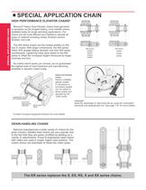
SPECIAL APPLICATION CHAIN SPECIAL APPLICATIONS CHIAN HIGH PERFORMANCE ELEVATOR CHAINS* Rexnord® Heavy Duty Elevator chains have garnered a reputation as the longest lasting, most reliable chains available today for tough elevating applications. Our chains are the most efficient and reliable to elevate all types of material including clinker, finished cement, fertilizer, and coal. The 900 series chains are the newest addition to this line of chains. With larger components, the 900 series offers 30% greater fatigue strength over their 800 series counterparts. Lightening holes were added to the...
Open the catalog to page 6
SPECIAL APPLICATION CHAIN From time to time, chain application questions concerning driving or conveying functions on amusement rides and recreational lifts are brought to Rexnord’s attention. Concern arises for the safety and the well being of people utilizing these units should chains prematurely or unexpectedly fail. A general review has been made to establish certain rules and recommendations for the selection and application of these rides and conveyances. The following reflects those conclusions: 1. Chain should not be used for any amusement ride or recreational lift application unless...
Open the catalog to page 7All Rexnord Industries, LLC catalogs and technical brochures
 1000 series
8 Pages
 Thomas XTSR Couplings
4 Pages
 CMR series
2 Pages
 111-210 AirMax-WEB
12 Pages
 Falk? Truehold Backstops Catalog
26 Pages
 Falk? Omnibox® Worm Gear Drives
146 Pages
 Rexrnord® Planetgear? Gear Drives
134 Pages
 Viva? Coupling Catalog
20 Pages
 Thomas® Coupling Catalog
44 Pages


Archived catalogs
 Link-Belt Drive and Roller Chain Catalog
114 Pages
 Rexnord® Mill Duty Bearing Catalog
20 Pages
 Marbett® Conveyor Components Catalog
32 Pages


