
- Catalogs
- Rexnord Industries, LLC
- Falk? Omnibox® Worm Gear Drives


Falk? Omnibox® Worm Gear Drives

Falk? Omnibox® Worm Gear Drives
1. Determine Required Input Horsepower: Calculate equivalent horsepower by multiplying motor horsepower by the Service Factor.
2. Determine Driver Output Speed and Ratio: Calculate gear drive output rpm by multiplying head shaft speed by chain drive ratio.
3. Select Drive Type and Size: Refer to specific pages for drive configuration and size selection based on required ratio and mechanical rating.
4. Check Overhung Load: Use tables to ensure overhung load capacities are not exceeded.
5. Check External Thrust Load: Verify allowable thrust loads and consult the factory if loads exceed capacities.
6. Check Gear Drive Dimensions: Refer to specific pages for dimensions based on the type of reduction.
Catalog excerpts

Falk™ Omnibox® Worm Gear Drives The Right Quality, The Right (English-Inch) Performance
Open the catalog to page 1
FALK™ OMNIBOX® The High-Performance Choice for all Your Applications When it comes to winning solutions to your right angle, small worm gear drive challenges, Omnibox has it all. Omnibox incorporates our best durability and reliability features into one competitively priced product line. Over 475,000 configurations mean there’s one that’s precisely right for virtually every application. And Omnibox delivers all this quality and performance in a package that offers drop-in convenience for minimal downtime. Omnibox Truly is the Best of the Best • Sizes: 1.33" through 10" centers • Output speeds:...
Open the catalog to page 2
For top performance even in extreme work environments, Omnibox drives feature the strength and rigidity of cast iron housings. High-strength steel output shafts resist failure from starting and stopping torque, shock loads and fatigue, while low-speed, heavy-duty tapered roller bearings withstand high overhung and thrust loads. throughout the life of the drive. The single cover output design ensures gear centering for maximum efficiency, with minimal noise levels. In addition, chill-cast bronze gears help assure long, trouble-free life and quality operation. And hardened and precision ground...
Open the catalog to page 3
Omnibox Selection Guide 4
Open the catalog to page 4
Selection Guide 271-108, November 2000 Table of Contents Reference Notes Omnibox General Information W Basic Information . . . . . . . . . . . . . . . . . . . . . . . . . . . . . . . . . . 6 Conditions Affecting Selection . . . . . . . . . . . . . . . . . . . . . . . . . 7 How to Select and Order — Quick Selection Method . . . . . . . . 8 Drive Nomenclature . . . . . . . . . . . . . . . . . . . . . . . . . . . . . . . . 9 Service Factors . . . . . . . . . . . . . . . . . . . . . . . . . . . . . . . . 10-11 Overhung Load and Thrust . . . . . . . . . . . . . . . . . . . . . . . 12-13 Selection...
Open the catalog to page 5
Basic Information Safety Notes Gear Drive Ratings Falk Gear Drives The Falk and Rexnord name on the gear drive is the purchaser’s assurance that the drive was engineered, rated and manufactured to sound design practices. The power supplied to the geared drive must be equal to or less than the power for which the drive was selected using the appropriate service factor for the application. The customer must also assume the responsibility of isolating the geared drive from any vibratory or transient load induced by the driven equipment. Install and operate Rexnord products in conformance with applicable...
Open the catalog to page 6
Conditions Affecting Selection Non-Standard Application Procedures The following conditions may affect the Omnibox gear drive selection procedure, drive size, and auxiliary equipment being furnished. Excessive Overloads The maximum momentary or starting load must not exceed 200% of rated load (100% overload). Rated load is defined as gear drive rating with a service factor of 1.0. If the maximum starting or momentary load exceeds the above conditions, compute a second equivalent power rating by dividing the peak load by two. The gear drive selected must have capacity equal to, or in excess of,...
Open the catalog to page 7
How to Select and Order Quick Selection Method Example 1. Determine Service Factor — Pages 10 and 11. 2. Determine Required Input Horsepower — Calculate the equivalent hp by multiplying the motor hp by the Service Factor. 3. Determine Driver Output Speed and Ratio. 4. Select Drive Type and Size — Refer to Pages 14 through 19 and select the desired drive configuration. Then refer to Pages 22 through 27 (Single Reduction), Pages 52 through 57 (Double Reduction, Worm-Worm), or Pages 82 through 85 (Double Reduction, Helical Worm) and select the drive size. Locate the table containing required ratio,...
Open the catalog to page 8
Drive Nomenclature 1133 WBQM 2 A P 30 AH 125 DRIVE SIZE PRODUCT TYPE ASSEMBLY NUMBER HOLLOW LOW SPEED SHAFT BORE SIZE MODEL MOTOR FRAME SIZE SEALED DRIVE RATIO Drive Size (Shaft Centers) 1133 = 1.33 1154 = 1.54 1175 = 1.75 1206 = 2.06 1238 = 2.38 1262 = 2.62 1300 = 3.00 1325 = 3.25 1326 = 3.26 1425 = 4.25 Motor Frame Size 1525 = 5.25 1600 = 6.00 1700 = 7.00 1800 = 8.00 11000 = 10.00 Product Type W Expressed 2 to 5 letters, including Primary Type, Output Shaft, and Motor Flange, as required. WB — Basic drive without Feet (Single Reduction) WU — Worm Under (Horizontal LSS) WO — Worm Over (Horizontal...
Open the catalog to page 9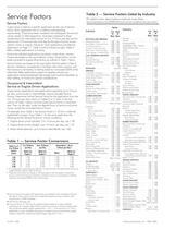
Table 2 — Service Factors Listed by Industry Service Factors (For electric motor, steam turbine or hydraulic motor drives . . . recommendations are MINIMUM and normal conditions are assumed.) Service Factors A gear drive is rated to a specific application by the use of Service Factor. Each application has its conditions and operating requirements. These have been analyzed and catalogued. Numerical values, based on field experience, have been assigned to these classifications for intermittent service of 3 to 10 hours per day and for service over 10 hours per day and also for the type of prime...
Open the catalog to page 10
Table 3 — Service Factors Listed by Application (For electric motor, steam turbine or hydraulic motor drives . . . recommendations are MINIMUM and normal conditions are assumed.) Service Application 3 to Over 10 10 Hour Hour Application Service 3 to Over 10 10 Hour Hour Service Application 3 to Over 10 10 Hour Hour Service Application 3 to Over 10 10 Hour Hour AGITATORS PUMPS s CONVEYORS—Uniformly s HOISTS Pure Liquids . . . . . . . . . . . . . . . 1.00 loaded or Fed: 1.25 Heavy Duty. . . . . . . . . . . . . . . . 1.75 Centrifugal . . . . . . . . . . . . . . . . 1.00 2.00 1.25 Liquids & Solids...
Open the catalog to page 11
Overhung Load and Thrust Loads Load Connection Factor (Fc) Overhung Load — Overhung load is imposed upon a shaft when a pinion, sprocket, or sheave is used as a power take-off. The magnitude of the load varies with the type of take-off and its proximity to the shaft bearing. Calculate the load (including minimum required service factor) and check the result against the tabulated overhung load rating. The overhung load formula below considers the transmitted horsepower without service factor. This is appropriate for applications where starting loads, momentary overloads, and brake capacities do...
Open the catalog to page 12All Rexnord Industries, LLC catalogs and technical brochures
 1000 series
8 Pages
 Thomas XTSR Couplings
4 Pages
 CMR series
2 Pages
 111-210 AirMax-WEB
12 Pages
 Falk? Truehold Backstops Catalog
26 Pages
 Rexrnord® Planetgear? Gear Drives
134 Pages
 Viva? Coupling Catalog
20 Pages
 Thomas® Coupling Catalog
44 Pages


Archived catalogs
 Link-Belt Drive and Roller Chain Catalog
114 Pages
 Rexnord® Mill Duty Bearing Catalog
20 Pages
 Marbett® Conveyor Components Catalog
32 Pages


