3D geophone wireless
1 /5Pages

3D geophone wireless
1 /5Pages
Catalog excerpts

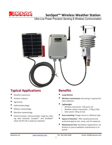
SeniMax™ 3D Wireless Geophone Ultra-Low Power Precision Sensing & Wireless Communication Typical Applications ▪ Seismic monitoring ▪ General structural integrity Benefits ▪ Long lifetime ▪ A Stand-alone IoT Device: all-in-one device (buildings, dams, tunnels, etc.) Platform stabilization systems capable of sensing, collecting and uploading data Seismic imaging Serve as a gateway (SeniMax™) to upload the data to server Easy mounting: Flange mount or adhesive tape sensing element (separated from transceiver) Ingress Protection: IP66, weatherproof and protected against rain, snow, and UV exposure
Open the catalog to page 1
Maintenance free: Self-powered by a solar panel. No battery replacement, calibration or post-installation maintenance is required Adjustable threshold and sample interval Dimensions (Transceiver): 215.9mm (8.50”)× 170.69mm (6.72”) × 131.75mm (5.19”) Dimensions (Sensing Element with flange): 149.12 (5.81”) × 80.00 (3.15”) × 60.50 (2.38”) Weight: 1.5kg (3.3lbs) transceiver and 0.9kg (2lbs) sensing element Operating temperature: -40°C to +65°C (-40°F to +150°F) Wireless Communication: Cellular (CDMA, GPRS, HSPA+, LTE) or Wi-Fi (IEEE 802.11 b/g) Wireless communication range: 1.0km (0.62mi) free space...
Open the catalog to page 2
ments within a specific time period after installing the sensor and based on actual condition. Also, the sampling interval can be adjusted remotely from 2ms (500Hz) to 100ms (10 Hz) after installation based on application requirements. For more detailed information about the Geophone unit, please see the product datasheet which can be found from: https://www.geospace.com/products/sensors/hs1/ Installation Sensing element box is separate from transceiver and comes with mounting flanges. It can be installed either with screws and anchors through the flange holes or with VHB adhesive tape (for steel...
Open the catalog to page 3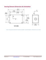
Sensing Element Dimension & Orientation Figure 2: Sensing element dimension & orientation for SeniMax™ wireless 3D Geophone. All dimensions are in mm [inch]. Email: [email protected]
Open the catalog to page 4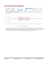
The data shown in SenScope™ Figure 3: Geophone X axis data This picture (Figure 3) shows the X-axis measurement of the Geophone. When there is no vibration over the threshold, the Geophone will only transmit keep-alive packets. When there is vibration, it will transmit and keep measuring for a period of time even after the vibration drops below the threshold. Email: [email protected]
Open the catalog to page 5All Resensys catalogs and technical brochures
 VibrationSenSpot
2 Pages
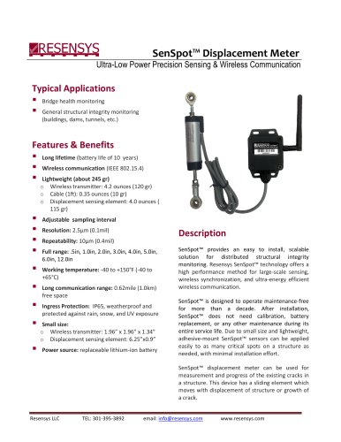
 SenSpot™ Displacement Meter
4 Pages
 New Brochure
24 Pages
 New SeniMax Wi-Fi
2 Pages
 New SenScope
4 Pages


Archived catalogs
 New SeniMax
2 Pages
 New Displacement SenSpot
4 Pages
 New Temperature SenSpot
2 Pages
 New Tilt SenSpot
3 Pages
 New Vibration SenSpot
3 Pages
 New Strain SenSpot
4 Pages
 SenScope™
2 Pages
 SenSpot™ Vibration Datasheet
2 Pages
 SenSpot™ Humidity Datasheet
2 Pages
 SenSpot™ Strain Datasheet
3 Pages
 SenSpot™ Inclination/Tilt
3 Pages
 TiltSenSpot2D
3 Pages


- BIO-UV flow meter
- Temperature probe
- Volume flow monitor
- Liquid flow monitor
- BIO-UV measuring instrument
- Management software solution
- Analysis software solution
- Windows software
- Real-time software
- Acceleration sensor
- Monitoring software solution
- Waterproof temperature sensor
- Thermocouple temperature transducer
- Water flow monitor
- Tilt sensor
- Visualization software solution
- Humidity and temperature probe
- Displacement transducer
- Single-axis accelerometer
- Linear displacement sensor