

WM Series Wormgear Unit

WM Series Wormgear Unit
The WM Series wormgear units are designed for high torque capacity and efficiency, featuring a unique Holroyd tooth profile. The gear case is made from close grain cast iron for strength and vibration absorption, ensuring quiet operation. The modular design allows integration with other Renold products, extending torque, ratio, and speed capabilities. Key features include a phosphor bronze wormwheel rim electron beam welded to a cast iron center, a sprag clutch backstop option, and heavy-duty taper roller bearings for maximum load capacity.
The gear units are classified as ATEX Group II Category 2 equipment, suitable for use in potentially explosive atmospheres. Regular maintenance is essential to prevent oil leakage and overheating. The maximum surface temperature must not exceed 135°C (T4), with a higher temperature class T3 available under certain conditions.
The gear cases are precision-machined for oil tightness and accurate gear location. The wormshaft is made from alloy steel, casehardened, and polished. The wormwheel rim is bronze, electron beam welded to the cast iron center. The Holroyd gear form ensures uniform angular velocity and efficient lubrication.
The WM Series offers various design options, including hollow output shafts, dry well adaptations for non-leak units, and agitator versions with solid output shafts for mixer applications. Double reduction units are available with ratios from 75:1 to 4900:1.
The WM Series units can be mounted in various configurations, including underdriven, overdriven, and vertical positions. Sprag backstops can be fitted to prevent run-back.
The document provides detailed specifications for electric motors compatible with the WM Series, including power ratings, full-load current, speed, and efficiency.
To order a WM Series unit, the full designation code must be provided, including unit type, size, and any additional features such as a sprag clutch holdback.
Specifications:
The WM Series motorised units are defined by several key specifications including unit type, size, nominal ratio, mounting assembly, motor power, motor speed, IEC frame sizes, and shaft/bore details. The nominal ratios available are 5:1, 10:1, 30:1, etc.
To select a worm gear unit, essential information such as power requirements, speed, duty characteristics, and working conditions must be provided. For input speeds below 250 rev/min, consultation with the Technical Sales Department is recommended.
When ordering, it is important to quote the catalogue reference, shaft assembly number, and nominal ratio. Non-standard mounting positions should be indicated with a sketch.
The mechanical powers listed are for 10 hours of daily operation with a service factor of 1.0. Service factors should be applied for non-uniform loading or different working hours.
Efficiency figures are approximate and depend on the gearbox being fully run-in and operating under full load. Cooler lubricant may reduce efficiency due to increased oil churning losses.
Thermal ratings are based on an ambient temperature of 20˚C. Exceeding these ratings continuously can lead to overheating. The thermal service factor should be applied if ambient temperatures exceed 20˚C.
The selection process involves determining the required gear ratio, load classification, and applying service factors to the absorbed power. The thermal rating must also be checked for continuous operation.
Applications are classified by load characteristics: steady, medium impulsive, and highly impulsive. Service factors are provided for different prime movers and durations of service.
Output shafts may experience overhung loads from attachments like pinions or pulleys. If loads exceed the unit's capacity, larger units or additional bearings may be necessary.
Two examples illustrate the selection process for different applications, considering mechanical and thermal ratings, service factors, and oil type.
- Efficiency: Efficiency percentages range from 82.1% to 94.8% depending on the configuration and load conditions.
- Input Power: Input power is measured in kilowatts (kW) for both thermal and mechanical inputs, with values provided for different operational scenarios.
- Output Torque: Output torque is provided in Newton-meters (Nm) for both thermal and mechanical outputs, indicating the torque capacity under various conditions.
- Maximum torques are specified for uniform load applications with a maximum of 5 starts per hour. For applications involving high torques, overhung loads, or frequent starts, consultation with Renold is recommended.
- For the WM 9 unit, torques exceeding the stated maximum require the specification of two keyways and a high tensile steel output shaft.
- Gear ratings and performance data are provided for both mineral and synthetic oils, with specific input power and torque values for different center distances and nominal ratios.
- Efficiency and performance data are presented for nominal ratios of 15/1, 20/1, 25/1, and 30/1, with detailed tables showing input power, output torque, and efficiency percentages for each configuration.
- Maximum standard shaft torque values are provided, with specific notes on configurations that require additional specifications for higher torque applications.
The WM unit features a solid shaft design. It includes various mounting options such as single and double extension foot and flange mounts. The document provides detailed dimensions for different unit sizes, specifying measurements for bolts, holes, and other components.
Units are supplied without oil and must be filled with lubricant before operation. Initial running should gradually increase load over 20 to 40 hours. Regular maintenance includes monthly oil level checks and ensuring ventilation. Oil should be changed based on working conditions. Bearings require grease lubrication, especially when wormshafts are vertical.
Units stored for long periods should be protected, especially in corrosive environments. If empty, spray with rust preventative oil. If filled, operate monthly to coat internal parts. For indefinite storage, fill completely with oil.
Use high-quality oils to prevent damage. Oils are categorized into light, medium, and heavy grades based on temperature and load conditions. Synthetic oils offer higher efficiency and longer life. Avoid certain EP additives that can damage bronze components.
Customers should seek additional guidance for safe product use. Performance levels are verified but not guaranteed for all applications. Information is subject to change, and products may vary from illustrations. Renold reserves the right to modify products.
Renold is a global power transmission group with an international network. For local sales and service, visit their website.
Catalog excerpts

Wormgear Units Imperial Gearing Centres Superior Gear Technology
Open the catalog to page 1
WM Series - Product Features Unique Holroyd tooth profile for maximum torque capacity Double extension Phosphor Bronze beam welded directly onto the cast iron centre ensuring maximum strength under shock load conditions. Hollow output shaft for direct mounting onto machine headshaft. Plug in heavy duty output shaft also Two piece close grain cast iron gear case for strength and absorption of vibrations for quiet running. Sprag clutch backstop option i prevent drive reversals. Heavy duty taper roller maximum load capacity tapped to allow fitting of output flange for greater mounting flexibility....
Open the catalog to page 2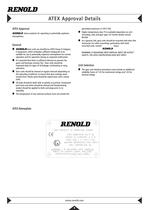
ATEX Approval Details ATEX Approval RENOLD Gears products for operating in potentially explosive 9 RENOLDGears units are classified as ATEX Group II Category 2 equipment, which embodies sufficient safeguards to be suitable for use in potentially explosive atmospheres for normal operation and for operation during an expected malfunction. 9 It is essential that there is sufficient lubricant to prevent the gears and bearings running 'dry'. Gear units should be inspected daily for signs of oil leakage, overheating or noisy 9 Gear units should be cleaned at regular intervals depending on the operating...
Open the catalog to page 4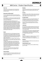
WM Series - Product Specification Gear Case Bearings The gear cases are of close grained cast iron with all joints and bearing bores accurately machined to ensure oil tightness and precise gear location. Standard metric taper/roller bearings are fitted throughout the WM Series range of units in both single and double extension shaft options. Oil Seals Wormshaft and Wormwheel Semi-dual lip oil seals are fitted to all hollow output shaft units and single lip seals are fitted to the input shaft of all unit sizes and the output of WM9 unit range and all agitator unit types. The worm is integral with...
Open the catalog to page 5
WM Series - Product Design Variations Hollow output shaft unit showing standard metric extension input shaft and American extension at the fan end. Standard hollow output shaft with semi dual lip oil seal for added oil retention. Underdriven unit with standard plug-in output shaft. Single and double extension shafts are available with metric American dimensions. Sprag Clutch, anti run-back assembly fitted to the fan extension end of the input shaft, to prevent unit run back. The Sprag Clutch can be supplied as a kit for retro fitting at any time. www.renold.com 6
Open the catalog to page 6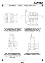
WM Series - Product Design Variations Dry well adaption fitted at the output of the WM Series unit. The non leak feature is particularly important on mixer applications in the food and chemical Industry. Unit fitted with output location flange and double extension output shaft, one standard extension and one longer than standard compensating for the flange. WMA - Agitator unit with output shaft down. The unit is shown with the dry well feature. The output shaft bearings have a greater bearing span to allow for higher external loads imposed by mixer and agitator blades. Agitator unit with output...
Open the catalog to page 7
^WM Series - Single Reduction - Mounting & Handling ^ WMSM - Shaft Mounted No Sprag backstop fitted. Sprag backstop fitted. No Sprag backstop fitted. Sprag backstop fitted. No Sprag backstop fitted. Sprag backstop fitted. No Sprag backstop fitted. Sprag backstop fitted. Wall Mounting No Sprag backstop fitted. Sprag backstop fitted. No Sprag backstop fitted. Sprag backstop fitted.
Open the catalog to page 8
^WM Series - Single Reduction - Mounting & Handling^ No Sprag backstop fitted. VA Sprag backstop fitted. VB No Sprag backstop fitted. Sprag backstop fitted. No Sprag backstop fitted. Sprag backstop fitted. No Sprag backstop fitted. Sprag backstop fitted. No Sprag backstop fitted. Sprag backstop fitted.
Open the catalog to page 9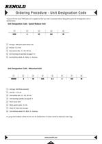
Ordering Procedure - Unit Designation Code To ensure that the correct ‘WM’ Series unit is supplied and that your order is processed without delay, please quote the full designation code as detailed below: Unit Designation Code - Speed Reducer Unit 1 2 3 4 5 WM 4 10 UA M 1 Unit type - WM Series speed reducer unit 2 Unit size - 4, 5, 6 etc. 3 Unit nominal ratio - 5:1, 10:1, 30:1 etc 4 Unit mounting and assembly see pages 8 - 9 5 Unit shaft/bore details M - Metric A - American Unit Designation Code - Motorised Unit 1 2 3 4 5 6 7 8 MWM 4 10 WA 5.5 4 132 M 1 Unit type - WM Series motorised 2 Unit...
Open the catalog to page 12
WM Series - Selection Information To select a worm gear unit the following basic information must be known and, if we are to make the selection, should be submitted in full to our Technical Sales Department. Power a) Prime mover, type and output power (kW). b) Gear unit input and output power required (kW). c) For input speeds below 250 rev/min consult our Technical Sales Department giving details of required output torque (Nm) and diameter of driven shaft (mm). Speed Gear unit input and output rev/min. Duty a) The characteristics of the drive eg. degree of impulsiveness of the driven load. b)...
Open the catalog to page 13
WM Series - Selection Examples Mechanical Selection Torque Thermal Selection Torque Mechanical Selection Power Thermal Selection Power Nm = Nm = (kW) = (kW) = Actual Torque (Nm) Requirement Actual Torque (Nm) Requirement Actual Power (kW) Requirement Actual Power (kW) Requirement It can be seen from the ratings tables on pages 28 - 41 that both mineral and synthetic oil ratings are included. Depending upon which type of oil is to be used inside the gear unit will determine which rating are used to make a selection. Example 1 X X X X Mechanical Service (fD) Factor Thermal Service (fT) Factor Mechanical...
Open the catalog to page 14
^ WM Series - Load Classification by Application ^ Pure liquids Liquids-variable density Brew kettles-continuous duty S Mash tubs-continuous duty S Scale hopper-frequent starts M Clay working machinery Clay working machinery M Reciprocating - single cylinder H Conveyors - uniformly loaded or fed Conveyors - heavy duty Live roll * Crane Drives - not dry dock Bridge travel * Trolley travel * Cable reels Cutter head drives Manoeuvring winches Screen drive Utility winches Main hoist Auxiliary hoist Boom, luffing Rotating, swing or slew Tracking, drive wheels Bucket - uniform load Bucket - heavy load...
Open the catalog to page 15All RENOLD catalogs and technical brochures
 Corrosion Resistant
6 Pages
 RENOLD SD
8 Pages
 Renold Syno
12 Pages
 Conveyor Brochure
80 Pages
 Transmission - Catalogue
100 Pages
 RENOLD A&S
6 Pages
 General Products
12 Pages
 Renold Roller Chain
4 Pages
 Lifting - Catalogue
24 Pages
 Roll-Ring
8 Pages
 Standard Conveyor
8 Pages
 Renold Klik-Top
4 Pages
 Renold Sovereign
4 Pages
 Spiderjaw & Spiderwrap Couplings
10 Pages
 Chainflex Coupling
14 Pages
 Gearflex Coupling
20 Pages
 UJ Coupling
2 Pages
 RB & PM Catalogue
36 Pages
 Hi-Tec General Catalogue
60 Pages
 Renold Synergy
8 Pages
 PM Series PW Type Wormgear Unit
68 Pages
 jPM Series Wormgear Unit
52 Pages
 Crownpin Couplings
12 Pages
 Pinflex Couplings
14 Pages
 Tyreflex Couplings
12 Pages
 Hydrastart Coupling
22 Pages
 VF Coupling
8 Pages
 MSC catalogue
16 Pages
 Sprag Cage Assemblies
3 Pages
 Universal Joints
28 Pages
 Mill Spindles
20 Pages
 RP Series
76 Pages
 TW Series
44 Pages
 Transmission Chain
94 Pages
 Conveyor Chain
80 Pages
 Lifting Chain
24 Pages




Archived catalogs
 Universal Gears Catalogue
846 Pages
- Right angle gearhead
- Compact gearhead
- Shaft shaft coupling
- Gear train gear reducer
- Transmission gearhead
- Transmission chain
- Shaft gearhead
- Helical gear gearhead
- Flange coupling
- Metal chain
- Vibration motor
- Clamp gearbox
- Torque coupling
- Transfer chain
- Bevel gearhead
- Modular gearhead
- Transmission coupling
- Roller chain
- High load capacity gear reducer