

Universal Joints

Universal Joints
Renold Inc. provides a range of universal joints known for their durability, high shock and overload capacity, and minimal lubrication needs. These joints are designed for quick delivery and are nearly backlash-free.
Renold Universal Joints are manufactured domestically with high torque capacity and long bearing life. They feature a one-piece yoke and bearing housing, eliminating unnecessary bolted connections. Made from heat-treated alloy steel, they ensure optimal loading across the bearing length. Available in four basic types, they come with technical support and engineering services.
These joints are used in industries such as metals, agriculture, marine, mining, oil and gas, and packaging. Applications include agitators, compressors, conveyors, cranes, generators, and pumps.
Universal joints come in seven basic bearing designs, with series accommodating various sizes and types. Speed limits are determined by mass acceleration and lateral critical speed, with guidelines for balancing requirements.
A detailed selection procedure ensures the appropriate joint is chosen based on application needs.
Comprehensive data covers flange adapters, design variations, kinematics, motion characteristics, bore tolerances, and weights.
Renold Universal Joints are engineered for demanding applications, offering high misalignment angles and robust designs that resist lubrication loss and contamination.
- Mass Acceleration: Irregular movement at angles greater than zero leads to mass acceleration torque, which must not exceed limits.
- Lateral Critical Speed: For long shafts, speed is limited by lateral critical speed, which depends on tube diameter, wall thickness, and length. Operating speed should be less than 75% of this speed to avoid vibration.
Joints under 300 RPM are unbalanced; those between 300-850 RPM are balanced if needed. Above 850 RPM, balancing is standard.
- Endurance Torque (Te): Normal rating for fully reversing torque.
- One Way Endurance Torque (Tow): Rating for pulsating one-way torque.
- Life Torque (TL): Based on B-10 bearing life, indicating a 90% survival probability.
- Peak Torque (Tp): Maximum allowable torque based on yield strength.
- Calculate application torque (Ta) and selection torque (Ts).
- Ensure life expectancy using B-10 life calculations.
- Consider duty cycle for varying conditions.
- Ensure peak torque conditions are met.
- Consider diameter, length, bore size, and speed limits.
A cold mill with a 1800 HP motor at 400 RPM requires two universal joints. Calculations for application torque, life expectancy, and peak torque lead to selecting RA315 with specific design adaptors.
Telescopic splines accommodate movement, and axial forces are calculated based on torque, angle, and spline diameter. Custom solutions are available for unique conditions.
This document provides technical specifications and design considerations for shafts and flange connections, focusing on torque ratings, dimensional data, and design variations. It includes metric and imperial measurements for various sizes and applications.
Torque ratings for different shaft sizes include normal fully reversing torque (Te), normal pulsating one-way torque (Tow), B-10 bearing life rating (Tl), and peak torque (Tp). Dimensional data is provided in inches and millimeters for components like flange yokes and bolt quantities.
Recommendations are made for when selection torque approaches endurance torque or maximum torque nears peak capacity. Integral face pads or Hirth radial tooth connections are suggested. The document also discusses verifying flange connection capacity near material strength limits.
Specialty shafts, including torsionally dampened driveshafts, are designed to reduce torsional stress and resonance. Custom designs are available for specific applications like dynamometers and construction machines.
Universal joints exhibit non-uniform motion when operated at an angle. The driven yoke rotates non-uniformly in terms of angular displacement, velocity, and acceleration. To mitigate non-uniform motion, two joints can be arranged in tandem in a “Z” or “W” configuration.
Synchronous rotation is achievable if all shaft sections lie in the same plane, bearing bores of inboard yokes are in the same plane, and bend angles are equal, resulting in homokinetic operation.
Standard bore tolerances conform to AGMA 9002-A86 standards. Bores are typically furnished with an interference fit unless specified otherwise.
Weights of universal joints at minimum length are provided for various types, varying based on applications.
- Motor Specifications: Includes RPM, horsepower, and overload rating.
- Reducer and Shaft Details: Covers reducer ratio, pinion centers, shaft separation, and bore requirements.
- Work Roll Specifications: Details on work roll diameter and centers.
- Operating Angles: Maximum operating angle at full load and roll change angle at no load.
- Motor and Drive Configuration: Information on motor horsepower, RPM, reduction ratio, and service factor.
- Shaft and Load Requirements: Includes shaft separation, load offset, axial travel, and orientation.
- Environmental and Special Conditions: Operating environment, diameter restrictions, and special equipment interface requirements.
- Renold Inc. and Renold Canada Ltd. contact details for customer service and inquiries.
- Document includes a disclaimer about potential errors and changes post-publication.
- Renold Inc. is an ISO 9001 certified company.
Catalog excerpts
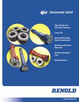
Universal Joint High Shock and Overload Capacity Long Life Heat Treated Alloy Steel Components Minimal Lubrication Required Virtually BacklashFree Quick Delivery Superior Technology www.renold.com
Open the catalog to page 1
16 AM Advantages and Design: Typical Applications Advantages and Features Typical Applications • Domestic manufacture Following is a partial list of applications for the Renold Universal Joint. • High torque capacity • Long bearing life Agitators Packaging • High operating angle capability Balancing Machines • One piece yoke and bearing housing construction Blowers and Fans • Eliminates unnecessary bolted connections and serrations in yokes Compressors • Heat treated alloy steel components Conveyors • Ideal loading across entire bearing length due to balanced deflection between yokes and cross...
Open the catalog to page 3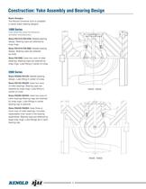
Construction: Yoke Assembly and Bearing Design Basic Designs The Renold Universal Joint is available in seven basic bearing designs: 1000 Series Yoke assembly parts furnished by domestic manufacturers. Sizes RA1310-RA1550: Needle bearing design. Bearing caps are retained by snap rings. Sizes RA1610-RA1880: Needle bearing design. Bearing caps are retained by bolts. Sizes RA1990: Uses two rows of roller bearings. Bearing caps are retained by snap rings. Lube tting in center of cross. 2000 Series Sizes RA058-RA100: Needle bearing design. Lube tting in center of cross. Sizes RA120-RA225: Uses two...
Open the catalog to page 4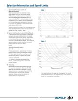
17 AM Selection Information and Speed Limits Table 1 RA1310 - RA225 RA250 RA250 3200 RA285 RA315 RA350 A RA390 RA435 A I. Speed Limit Based on Limits of Mass Acceleration When universal joints are operated at any angle greater than zero, the center section of the universal joint always runs irregularly, being accelerated and decelerated twice in every revolution. The maximum values of mass acceleration torque arising here are dependent on the operating speed and angle of deviation ß and upon the moment of inertia of the center shaft section [ RPM x A ]. To ensure smooth running of the universal...
Open the catalog to page 5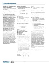
Selection Procedure See pages 26-27 for Application Data sheets for easy selection. Four types of torque ratings are given for each joint size. Universal Joint Selection I. Calculate application torque (Ta) and selection torque (Ts). Ta = HP x 63025 ( lb. x in. ) N Endurance torque (Te) is the normal rating for fully reversing torque based on material strength. One way endurance torque (Tow) is the normal rating for pulsating one way torque based on material strength. Life torque (TL) is the bearing life rating of the universal joint. This torque is based on the B-10 life of the universal joint...
Open the catalog to page 6
17 AM Axial travel of the telescopic spline on ST and FT designs under torque results in axial forces being applied to the support bearings. These forces are a function of the spline coefcient of friction, operating torque, operating angle, and spline pitch diameter per the following formula. F axial = 2T(µ)(COS A) PD F axial = Axial Force T= Operating Torque µ= Coefcient of Friction (.11 to .15 for lubricated steel on steel, contact Renold for other coatings) A= Operating Angle (degrees) PD = Table 3: Service Factors Load Driven Equipment Continuous Non-Reversing Drivers AC Motors Turbines Constant...
Open the catalog to page 7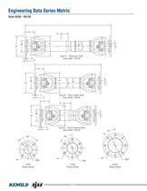
Engineering Data Series Metric Sizes RA58 - RA120 L K øA S øC øB β øD Type ST – Telescopic Shaft Sizes RA58 - RA120 E F L K øA øC øB Type SF – Fixed Length Shaft Sizes RA58 - RA120 E F K øA S øC øB E F 10 WE8491 APT MetalMillBroch.indd 10 45° 60° DBC 4 Bolt Flange Design β Type SC – Short Coupled Shaft Sizes RA58 - RA120 90° øH β øD øH øH DBC DBC 6 Bolt Flange Design 8 Bolt Flange Design 10 4/2/09 9:17 AM WE8
Open the catalog to page 10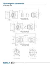
Engineering Data Series Metric Sizes RA120HD - RA225 L K øA S øC øB β øD Type ST – Telescopic Shaft Sizes RA120HD - RA225 E F L K øA øC øB E F β øD Type SF – Fixed Length Shaft Sizes RA120HD - RA225 L K øA S øC øB β Type SC – Short Coupled Shaft Sizes RA120HD - RA225 E F 45° 36° øH DBC øH 10 Bolt Flange Design 12 WE8491 APT MetalMillBroch.indd 12 DBC 8 Bolt Flange Design 12 4/2/09 9:17 AM WE8
Open the catalog to page 12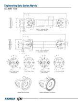
Engineering Data Series Metric Sizes RA250 - RA435 L K S X øA β øB øD Y E Type ST – Telescopic Shaft Sizes RA250 - RA435 øC F L K X øA β øB øD Y Type SF – Fixed Length Shaft Sizes RA250 - RA435 øC E F 45° 45° 36° 36° 22.5° 18° DBC øH øH 8 Bolt Flange Design with Face Key WE8491 APT MetalMillBroch.indd 14 øH 8 Bolt Flange Design Optional Face Pad Design 14 DBC DBC 10 Bolt Flange Design with Face Key øH DBC 10 Bolt Flange Design Optional Hirth Radial Tooth Design 14 4/2/09 9:17 AM WE8
Open the catalog to page 14
Engineering Data Series Metric Sizes RA440 - RA920 L K ØA ØB S X DBC ØD Y 45° 25.7° E ØC F Type FT TELESCOPIC SHAFT Shaft TYPE FT- – Telescopic SIZES U3440 - U3920 Sizes RA440 - RA920 ØH ØH 8 - HOLE ØA ØB DBC L 14 - HOLE K X ØD Y ØC E F Type FF- FIXED LENGTH SHAFT Shaft FF – Fixed Length TYPE SizesU3440 - U3920 RA920 SIZES RA440 - CAT26 22.5° ØH Face Key FACE KEY 16 - HOLE 16 - HOLE Flange Yoke Integral Face Pad Hirth Radial Tooth Connection 16 Hole The torque ratings are based on material strength. When approaching these limits the capacity of the desired ange connection should be veried. When...
Open the catalog to page 16
Torque Ratings Dimensional Data (inches and millimeters except where noted) Minimum Length L / Length Compensation S Torque Ratings Dimensional Data (inches and millimeters except where noted) Minimum Length L / Length Compensation S
Open the catalog to page 17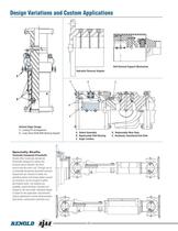
Design Variations and Custom Applications C B Roll Removal Support Mechanism A B Hydraulic Removal Adaptor A E A C B B CAT25 D Vertical Edger Design A. Locking Pin Arrangement B. Long Travel Shaft With Bearing Support A. Detent Assembly B. Replaceable Pilot Bearing C. Angle Limiters D. Replaceable Wear Keys E. Hardened, Chamfered End Plate Specialty Shafts Tosionally Dampened Driveshafts Renold offers torsionally dampened driveshafts designed to reduce the torsional stress between the drive source and the driven unit. Through use of a torsionally dampened driveshaft resonant frequencies are reduced...
Open the catalog to page 20All RENOLD catalogs and technical brochures
 Corrosion Resistant
6 Pages
 RENOLD SD
8 Pages
 Renold Syno
12 Pages
 Conveyor Brochure
80 Pages
 Transmission - Catalogue
100 Pages
 RENOLD A&S
6 Pages
 General Products
12 Pages
 Renold Roller Chain
4 Pages
 Lifting - Catalogue
24 Pages
 Roll-Ring
8 Pages
 Standard Conveyor
8 Pages
 Renold Klik-Top
4 Pages
 Renold Sovereign
4 Pages
 Spiderjaw & Spiderwrap Couplings
10 Pages
 Chainflex Coupling
14 Pages
 Gearflex Coupling
20 Pages
 UJ Coupling
2 Pages
 RB & PM Catalogue
36 Pages
 Hi-Tec General Catalogue
60 Pages
 Renold Synergy
8 Pages
 PM Series PW Type Wormgear Unit
68 Pages
 jPM Series Wormgear Unit
52 Pages
 Crownpin Couplings
12 Pages
 Pinflex Couplings
14 Pages
 Tyreflex Couplings
12 Pages
 Hydrastart Coupling
22 Pages
 VF Coupling
8 Pages
 MSC catalogue
16 Pages
 Sprag Cage Assemblies
3 Pages
 Mill Spindles
20 Pages
 RP Series
76 Pages
 TW Series
44 Pages
 WM Series Wormgear Unit
48 Pages
 Transmission Chain
94 Pages
 Conveyor Chain
80 Pages
 Lifting Chain
24 Pages




Archived catalogs
 Universal Gears Catalogue
846 Pages
- Right angle gearhead
- Compact gearhead
- Flexible coupling
- Shaft shaft coupling
- Gear train gear reducer
- Transmission gearhead
- Transmission chain
- Shaft gearhead
- Helical gear gearhead
- Flange coupling
- Metal chain
- Vibration motor
- Clamp gearbox
- Torque coupling
- Transfer chain
- Bevel gearhead
- Modular gearhead
- Transmission coupling
- Roller chain
- High load capacity gear reducer