Mill Spindles
1 /20Pages

Mill Spindles
1 /20Pages
Catalog excerpts
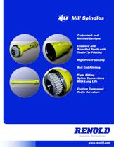
Mill Spindles Carburized and Nitrided Designs Crowned and Barrelled Teeth with Tooth-Tip Piloting High Power Density Roll End Piloting Tight Fitting Spline Connections With Long Life Custom Compound Tooth Curvature Superior Technology www.renold.com
Open the catalog to page 1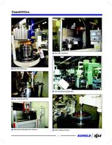
Capabilities New CNC machinery New CNC machinery Cell manufacturing approach Gear shaping machine New electro discharge wire machine CNC hobbing machine 3
Open the catalog to page 3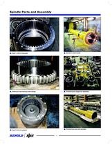
Spindle Parts and Assembly Type 1 roll end ring gear Spindle in paint booth Advanced load-sharing tooth design Finished parts staged for assembly Finished hot strip mill spindles Type 3 roll end adaptor 4
Open the catalog to page 4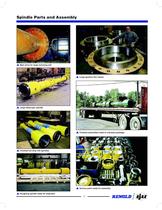
Spindle Parts and Assembly Main drive for large reversing mill Large gearbox ex halves Large telescopic spindle Finished assemblies head to overseas packager Finished hot strip mill spindles Various parts ready for assembly Roughing spindle ready for shipment 5
Open the catalog to page 5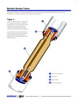
Spindle Design Types Design and construction characteristics balance the cost of the initial investment versus the cost to maintain the spindle over years of services. Renold offers basic designs. Type 1 1 Type 1 is normally used in smaller mills or in mills with restrictions on spindle diameters such as small minimum work roll diameter or pinion shaft center dimension. It features a high torque capacity with maximized pitch diameter. This spindle is the most economical in initial investment but the most costly to maintain because gear element replacement involves replacement of the entire ring...
Open the catalog to page 6
Spindle Design Types Continued Type 2 1 Type 2 provides the maximum pitch diameter and therefore the highest torque capacity like the Type 1 but uses a replaceable gear element to reduce maintenance costs. 2 3 4 5 1 2 Sleeve Ring Gear 3 Hub Gear 4 Center Shaft 5 7 Pinion End Adaptor Roll End Adaptor
Open the catalog to page 7
Spindle Design Types Continued 1 Type 3 The Type 3 offers the least possible cost in maintenance, but this economy in gear element replacement comes at the expense of torque capacity because the pitch diameter must be reduced relative to the outside diameter. 2 Highest initial cost for a given torque capacity is offset by economical maintenance costs in operation. 3 4 5 1 2 Ring Gear Insert 3 Hub Gear 4 Center Shaft 5 8 Pinion End Adaptor Roll End Adaptor
Open the catalog to page 8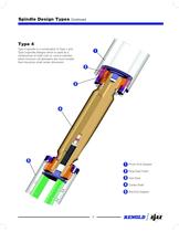
Spindle Design Types Continued Type 4 Type 4 spindle is a combination of Type 1 and Type 3 spindle designs which is used as a compromise of initial cost vs. cost to maintain when minimum roll diameters are much smaller than the pinion shaft center dimension. 1 2 3 4 5 1 2 Ring Gear Insert 3 Hub Gear 4 Center Shaft 5 9 Pinion End Adaptor Roll End Adaptor
Open the catalog to page 9
Continuous Circulating Oil Lubrication In order to address the inadequacies of grease lubrication, Renold has developed an oil lubricated spindle design for use in all types of mills including Hot Strip Roughing and Finishing applications. All types of spindles create heat through sliding contact under heavy compressive stress at the tooth anks of the contacting teeth. Conventional grease lubricated spindles rely on this heat to be emitted from the OD of the spindle. If the heat generation rate exceeds the rate at which the heat can be emitted, then the temperature will rise to unsafe levels....
Open the catalog to page 10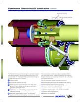
Continuous Circulating Oil Lubrication Continued Stationary housing Split oil transfer bearing 4 1 3 2 5 The Renold Continuous Circulating Oil Lubrication System provides a vehicle to remove this destructive heat. Oil is pumped onto the rotating spindle components through a transfer bearing, where it passes This process also ushes away any wear debris that occurs at the tooth anks, instead of allowing it to remain at the gear mesh to act as lapping compound, as is the case with grease lubrication. 1 radially inward, 2 through the center of the shaft, This Oil Lubrication System has been proven...
Open the catalog to page 11
Spindle Designs and Features These examples show some of the features of Renold Ajax Spindles that are currently in operation. Spherical Seal Single Lip Seal Rising Lip Seal Double Lip Seal Rising O-Ring Various Seal Options available on Renold Ajax Spindles Vertical Type 3 telescopic spindle for top driven bar mill 12
Open the catalog to page 12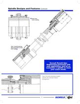
Spindle Designs and Features Continued Heavy duty motor coupling Consult Renold Ajax Engineering personnel with your application, and let us customize a spindle to meet your exact needs. Type 3 hot strip reversing rougher spindle with overload release arrangement 13
Open the catalog to page 13
Spindle Designs and Features Continued Type 3 telescopic spindle with spherical seals for single stand reversing (Steckel) mill with roll shifting Type 3 telescopic spindle for hot strip nishing stands with roll shifting Maximized tooth contact at load angle Single Curvature Single Compound Curvature Renold uses a compound curvature on the tooth ank to maximize the working area of the tooth, reduce Hertzian contact stress and vastly extend wear life. 14
Open the catalog to page 14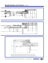
Spindle Designs and Features Continued Renold also uses a piloting system to reduce the action in the roll end bore without interfering with the roll change process. This system helps to reduce bore wear, reduce vibration and chatter, and improve product quality from the mill. 15
Open the catalog to page 15
Materials and Heat Treatment carrying teeth. Correcting distortion by lapping or grinding decreases the case depth. As with induction hardening 4140, carburizing’s low tempering temperature of 350o F to 400o F can lead to soft spots and rapid wear. In selecting gear spindle material, mill operating conditions, desired spindle service life and cost must be taken into consideration. Early gear spindles were made of medium carbon steel (AISI 1045), normalized and induction hardened for surface wear. This material and heat treatment is still used today, but the search for better performance and wear...
Open the catalog to page 16
Preliminary Spindle Coupling Selection Guide To guide the designer and user in preliminary selec- tion of mill spindle couplings, the following approach is recommended. Final selection is best handled by Renold application engineers. ■ Compute normal torque. ■ Select proper service factor. ■ Determine load / no load misalignment factor from Graph A. (The no load angle is critical - hold ■ Calculate design torque. ■ From Graph B or C, determine spindle diameter. ■ Cross check size with nominal bore and envelope limitations. ■ Send preliminary selection and required data to Renold for final evaluation...
Open the catalog to page 18All RENOLD catalogs and technical brochures
 Corrosion Resistant
6 Pages
 RENOLD SD
8 Pages
 Renold Syno
12 Pages
 Conveyor Brochure
80 Pages
 Transmission - Catalogue
100 Pages
 RENOLD A&S
6 Pages
 General Products
12 Pages
 Renold Roller Chain
4 Pages
 Lifting - Catalogue
24 Pages
 Roll-Ring
8 Pages
 Standard Conveyor
8 Pages
 Renold Klik-Top
4 Pages
 Renold Sovereign
4 Pages
 Spiderjaw & Spiderwrap Couplings
10 Pages
 Chainflex Coupling
14 Pages
 Gearflex Coupling
20 Pages
 UJ Coupling
2 Pages
 RB & PM Catalogue
36 Pages
 Hi-Tec General Catalogue
60 Pages
 Renold Synergy
8 Pages
 PM Series PW Type Wormgear Unit
68 Pages
 jPM Series Wormgear Unit
52 Pages
 Crownpin Couplings
12 Pages
 Pinflex Couplings
14 Pages
 Tyreflex Couplings
12 Pages
 Hydrastart Coupling
22 Pages
 VF Coupling
8 Pages
 MSC catalogue
16 Pages
 Sprag Cage Assemblies
3 Pages
 Universal Joints
28 Pages
 RP Series
76 Pages
 TW Series
44 Pages
 WM Series Wormgear Unit
48 Pages
 Transmission Chain
94 Pages
 Conveyor Chain
80 Pages
 Lifting Chain
24 Pages


Archived catalogs
 Universal Gears Catalogue
846 Pages
- Right angle gearhead
- Compact gearhead
- Flexible coupling
- Shaft shaft coupling
- Gear train gear reducer
- Transmission gearhead
- Shaft gearhead
- Transmission chain
- Helical gear gearhead
- Flange coupling
- Vibration motor
- Clamp gearbox
- Metal chain
- Torque coupling
- Bevel gearhead
- Modular gearhead
- Transfer chain
- Transmission coupling
- Roller chain
- High load capacity gear reducer