HTB-GS, DCB-GS and RB Generator and Pump Set Couplings
1 /36Pages
HTB-GS, DCB-GS and RB Generator and Pump Set Couplings
1 /36Pages
Catalog excerpts

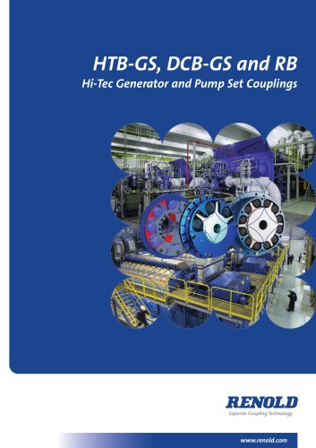
HTB-GS, DCB-GS and RB Hi-Tec Generator and Pump Set Couplings Superior Coupling Technology
Open the catalog to page 1
I HTB-GS, DCB-GS and RB Catalogue Introduction Over 60 years of experience Renold Hi-Tec Couplings has been a world leader in the design and manufacture of torsionally flexible couplings for over 60 years. Commitment to Quality and the Environment Having gained EN ISO 9001:2008, EN ISO 14001:2004 and EN ISO 18001:2007, Renold Hi Tec Couplings can demonstrate their commitment to quality, environment and occupational health and safety. World Class Manufacturing Continual investment is being made to apply the latest machining and tooling technology. The application of lean manufacturing techniques...
Open the catalog to page 2
HTB-GS, DCB-GS and RB Catalogue Contents Page No HTB-GS Coupling Features & benefits Flywheel mounted Technical data Design variations DCB-GS Coupling Features & benefits Dimensional Data Technical data Design variations RB Coupling Features & benefits Flywheel mounted Technical data Design variations Renold Gears and Couplings product range Health and Safety at Work Customers are reminded that when purchasing Renold products, for use at work or otherwise, additional and up-to-date information, which is not possible to include in Renold publications, must be obtained from your local sales office,...
Open the catalog to page 3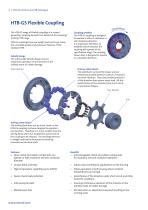
I HTB-GS, DCB-GS and RB Catalogue HTB-GS Flexible Coupling The HTB-GS range of flexible couplings is a second generation coupling derived from Renold Hi-Tec Couplings’ existing HTB range. Coupling rotation The HTB-GS coupling is designed to operate in either a clockwise or anti-clockwise direction. It is important, therefore, to establish which direction the coupling will operate at the specification stage. The coupling shown here is designed to operate in a clockwise direction. HTB-GS couplings have low weight and inertia yet retain the unrivalled quality and endurance features of the standard...
Open the catalog to page 4
HTB-GS, DCB-GS and RB Catalogue HTB-GS Standard SAE Flywheel to Shaft HTB-GS1600 - HTB-GS13300 Dimensions, Weight, Inertia and Alignment Coupling Size COUPLING SIZE A B B2 C D E F G J L M N Q R U V Y (MAX) Y (MIN) CHECK Per Cavity Per Coupling Rubber Driving Elements Maximum Speed [rpm] Weight W1 [kg] W2 W3 Inertia J1 [kg m²] J2 J3 Allowable Misalignment Radial [mm] Align Max Axial [mm] Align Max Conical [degree]
Open the catalog to page 5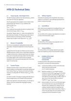
I HTB-GS, DCB-GS and RB Catalogue HTB-GS Technical Data 1.1 Torque Capacity - Diesel Engine Drives The HTB-GS Coupling is selected on the “Nominal Torque TKN”without service factors for Diesel Drive applications. The full torque capacity of the coupling for transient vibration whilst passing through major criticals on run up, is published as the maximum torque TKMAX . (TKMAX = 3 x TKN). There is additional torque capacity built within the coupling for short circuit and shock torques, which is 3 x TKMAX. The published “Vibratory Torque TKW”, relates to the amplitude of the permissible torque fluctuation....
Open the catalog to page 6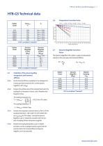
HTB-GS, DCB-GS and RB Catalogue | 7 HTB-GS Technical data
Open the catalog to page 7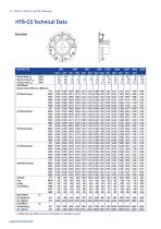
I HTB-GS, DCB-GS and RB Catalogue HTB-GS Technical Data End view COUPLING SIZE (1) Radial and axial stiffness values for other grades are available on request
Open the catalog to page 8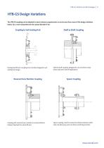
HTB-GS, DCB-GS and RB Catalogue HTB-GS Design Variations The HTB-GS coupling can be adapted to meet customer requirements as can be seen from some of the design variations below. For a more comprehensive list contact Renold Hi-Tec. Coupling to Suit Existing Hub Existing hub fitment. Coupling inner member designed to suit existing hub design. Reversed Inner Member Coupling Coupling with reversed inner member to increase distance between flywheel face and shaft end. Shaft to Shaft Coupling Shaft to Shaft Coupling. Designed for use on electric motor drives and power take off applications. Spacer...
Open the catalog to page 9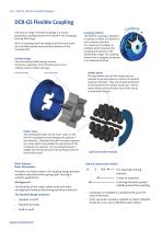
I HTB-GS, DCB-GS and RB Catalogue DCB-GS Flexible Coupling The DCB-GS range of flexible couplings is a second generation coupling derived from Renold Hi-Tec Couplings’ existing DCB range. DCB-GS couplings have low weight and inertia yet retain the unrivalled quality and endurance features of the standard DCB. Failsafe Design The intrinsically failsafe design ensures continuous operation of the driveline area in the unlikely event of rubber damage. Outer Member Coupling rotation The DCB-GS coupling is designed to operate in either a clockwise or anti-clockwise direction. It is important, therefore,...
Open the catalog to page 10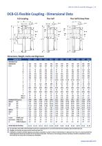
HTB-GS, DCB-GS and RB Catalogue DCB-GS Flexible Coupling - Dimensional Data Full Coupling Flex Half Flex Half & Keep Plate Dimensions, Weight, Inertia and Alignment COUPLING SIZE A B C D D1 E F G J K L Q R S T U MAX. X MAX. Y MAXIMUM SPEED (rpm) (1) WEIGHT W1 (kg) W2 (2) W3 W4 INERTIA J1 2 J2 (kgm ) (2) J3 J4 ALLOWED RADIAL (mm) MISALIGNMENT AXIAL (mm) (3) CONICAL (degree) PREFERRED SIZE DIMENSIONS (mm) (1) For operation above 80% of the declared maximum coupling speed, it is recommended that the coupling is dynamically balanced. (2) Weights and inertias are based on the maximum bore size. (3)...
Open the catalog to page 11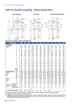
I HTB-GS, DCB-GS and RB Catalogue DCB-GS Flexible Coupling - Dimensional Data Full Coupling Flex Half Flex Half & Keep Plate Dimensions, Weight, Inertia and Alignment COUPLING SIZE PREFERRED SIZE DIMENSIONS A (mm) B C D D1 E F G J K L Q R S T U MAX. X MAX. Y MAXIMUM SPEED (rpm) (1) WEIGHT W1 (kg) W2 (2) W3 W4 INERTIA J1 2 J2 (kgm ) (2) J3 J4 ALLOWED RADIAL (mm) MISALIGNMENT AXIAL (mm) (3) CONICAL (degree) (1) For operation above 80% of the declared maximum coupling speed, it is recommended that the coupling is dynamically balanced. (2) Weights and inertias are based on the maximum bore size....
Open the catalog to page 12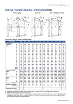
HTB-GS, DCB-GS and RB Catalogue DCB-GS Flexible Coupling - Dimensional Data Full Coupling Flex Half Flex Half & Keep Plate K Dimensions, Weight, Inertia and Alignment COUPLING SIZE PREFERRED SIZE DIMENSIONS A (mm) B C D D1 E F G J K L Q R S T U MAX. X MAX. Y MAXIMUM SPEED (rpm) (1) WEIGHT W1 (kg) W2 (2) W3 W4 INERTIA J1 J2 (kgm2) (3) J3 J4 ALLOWED RADIAL (mm) MISALIGNMENT AXIAL (mm) (3) CONICAL (degree) OPTION FOR SAE FLYWHEEL (1) For operation above 80% of the declared maximum coupling speed, it is recommended that the coupling is dynamically balanced. (2) Weights and inertias are based on the...
Open the catalog to page 13All RENOLD catalogs and technical brochures
 Corrosion Resistant
6 Pages
 RENOLD SD
8 Pages
 Renold Syno
12 Pages
 Conveyor Brochure
80 Pages
 Transmission - Catalogue
100 Pages
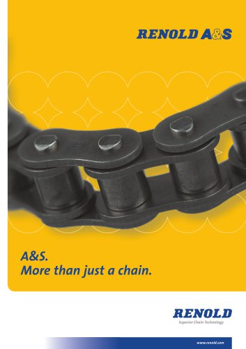 RENOLD A&S
6 Pages
 General Products
12 Pages
 Renold Roller Chain
4 Pages
 Lifting - Catalogue
24 Pages
 Roll-Ring
8 Pages
 Standard Conveyor
8 Pages
 Renold Klik-Top
4 Pages
 Renold Sovereign
4 Pages
 Spiderjaw & Spiderwrap Couplings
10 Pages
 Chainflex Coupling
14 Pages
 Gearflex Coupling
20 Pages
 UJ Coupling
2 Pages
 RB & PM Catalogue
36 Pages
 Hi-Tec General Catalogue
60 Pages
 Renold Synergy
8 Pages
 PM Series PW Type Wormgear Unit
68 Pages
 jPM Series Wormgear Unit
52 Pages
 Crownpin Couplings
12 Pages
 Pinflex Couplings
14 Pages
 Tyreflex Couplings
12 Pages
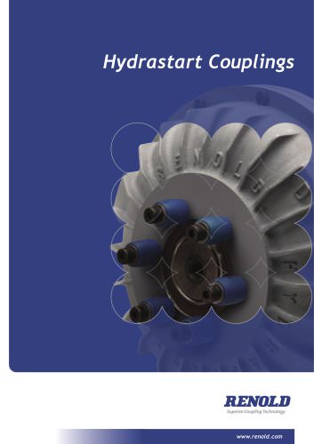 Hydrastart Coupling
22 Pages
 VF Coupling
8 Pages
 MSC catalogue
16 Pages
 Sprag Cage Assemblies
3 Pages
 Universal Joints
28 Pages
 Mill Spindles
20 Pages
 RP Series
76 Pages
 TW Series
44 Pages
 WM Series Wormgear Unit
48 Pages
 Transmission Chain
94 Pages
 Conveyor Chain
80 Pages
 Lifting Chain
24 Pages


Archived catalogs
 Universal Gears Catalogue
846 Pages
- Right angle gearhead
- Compact gearhead
- Gear train gear reducer
- Transmission gearhead
- Shaft gearhead
- Transmission chain
- Helical gear gearhead
- Flange coupling
- Vibration motor
- Clamp gearbox
- Metal chain
- Torque coupling
- Bevel gearhead
- Modular gearhead
- Transfer chain
- Transmission coupling
- Roller chain
- High load capacity gear reducer