Hi-Tec General Catalogue
1 /60Pages

Hi-Tec General Catalogue
1 /60Pages
Catalog excerpts

General Catalogue
Open the catalog to page 1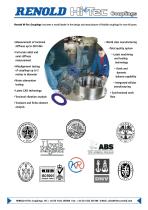
Renold Hi-Tec Couplings has been a world leader in the design and manufacture of flexible couplings for over 40 years. •Measurement of torsional stiffness up to 220 kNm •Full scale radial and axial stiffness measurement •Misalignment testing of couplings up to 2 metres in diameter •Noise attenuation testing •Latest CAD technology •Torsional vibration analysis • World class manufacturing •Total quality system • Latest machining and tooling technology • Static and dynamic balance capability • Integrated cellular manufacturing • Synchronised work flow •Transient and finite element analysis RENOLD...
Open the catalog to page 2
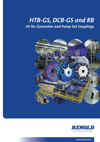
Contents Page No DCB Coupling Features & benefits Typical applications Series 6 Series 8 Series 10 Series 16 Technical data Design variations HTB Coupling Features & benefits Typical applications Flywheel mounted Technical data Design variations RB Coupling Features & benefits Typical applications Shaft to shaft Flywheel mounted Technical data Design variations PM Coupling Features & benefits Typical applications Shaft to shaft Mill motor couplings Technical data Technical data standard blocks Technical data special round blocks Design variations Selection Procedure Prime mover service factors...
Open the catalog to page 3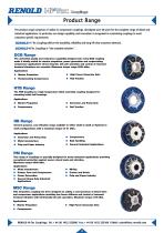
Product Range The product range comprises of rubber in compression couplings, developed over 40 years for the complete range of diesel and industrial applications. In particular, our design capability and innovation is recognised in customising couplings to meet customers specific requirements R ENOLD Hi -Tec Couplings deliver the durability, reliability and long life that customers demand. LD Hi-Tec Couplings is “the complete solution”. DCB Range The unrivalled quality and endurance capability designed into every DCB coupling make it ideally suited for marine propulsion, power generation and...
Open the catalog to page 4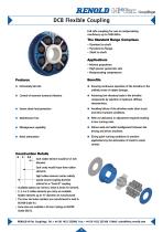
DCB Flexible Coupling Fail safe coupling for use on reciprocating machinery up to 5520 kNm. The Standard Range Comprises • Flywheel to shaft • Flywheel to flange • Shaft to shaft Applications • Marine propulsion • High power generator sets • Reciprocating compressors q Intrinsically fail safe q Ensuring continuous operation of the driveline in the unlikely event of rubber damage. q Achieving low vibratory loads in the driveline q Control of resonant torsional vibration components by selection of optimum stiffness characteristics. q Avoiding failure of the driveline under short circuit q Severe...
Open the catalog to page 5
Main propulsion. Couplings fitted between main engine and gearbox, gearbox and thrust block, and between thrust block and propulsion unit. Bio-gas generator sets. Coupling fitted between gas engine and alternator. Compressor sets. Coupling fitted between electric motor and compressor units. Rail traction. Coupling fitted between diesel engine and transmission via a universal joint shaft. Diesel generator sets. Couplings fitted between diesel engines and alternators, to provide electrical supply for ice breaker. RENOLD Hi-Tec Couplings. Tel: + 44 (0) 1422 255000 Fax: + 44 (0) 1422 255100 E-Mail:...
Open the catalog to page 6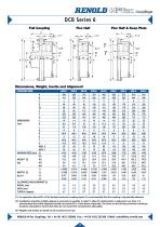
DCB Series 6 Full Coupling Flex Half Flex Half & Keep Plate Dimensions, Weight, Inertia and Alignment COUPLING SIZE COUPLING SIZE A B C D D1 E F G DIMENSIONS J (mm) K L Q R S T U MAX. X MAX. Y MAXIMUM SPEED (rpm) (1) W1 WEIGHT (3) W2 (kg) W3 W4 J1 INERTIA (3) J2 (kg m2) J3 J4 ALLOWABLE MISALIGNMENT (2) RADIAL (mm) AXIAL (mm) CONICAL (degree) (1) For operation above 80% of the declared maximum coupling speed, it is recommended that the coupling is dynamically balanced. (2) Installations should be initially aligned as accurately as possible. In order to allow for deterioration in alignment over...
Open the catalog to page 7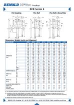
DCB Series 6 Full Coupling Flex Half Flex Half & Keep Plate Dimensions, Weight, Inertia and Alignment COUPLING SIZE COUPLING SIZE A B C D D1 E F G DIMENSIONS J (mm) K L Q R S T U MAX. X MAX. Y MAXIMUM SPEED (rpm) (1) W1 WEIGHT (3) W2 (kg) W3 W4 J1 INERTIA (3) J2 (kg m2) J3 J4 ALLOWABLE MISALIGNMENT (2) RADIAL (mm) AXIAL (mm) CONICAL (degree) (1) For operation above 80% of the declared maximum coupling speed, it is recommended that the coupling is dynamically balanced. (2) Installations should be initially aligned as accurately as possible. In order to allow for deterioration in alignment over...
Open the catalog to page 8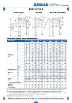
DCB Series 8 Full Coupling Flex Half Flex Half & Keep Plate W2 J2 Dimensions, Weight, Inertia and Alignment COUPLING SIZE COUPLING SIZE A B C D D1 E F G DIMENSIONS J (mm) K L Q R S T U MAX. X MAX. Y MAXIMUM SPEED (rpm) (1) W1 WEIGHT (3) W2 (kg) W3 W4 J1 INERTIA (3) J2 (kg m2) J3 J4 ALLOWABLE MISALIGNMENT (2) RADIAL (mm) AXIAL (mm) CONICAL (degree) (1) For operation above 80% of the declared maximum coupling speed, it is recommended that the coupling is dynamically balanced. (2) Installations should be initially aligned as accurately as possible. In order to allow for deterioration in alignment...
Open the catalog to page 9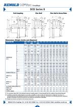
DCB Series 8 Full Coupling Flex Half Flex Half & Keep Plate W2 J2 Dimensions, Weight, Inertia and Alignment COUPLING SIZE COUPLING SIZE A B C D D1 E F G DIMENSIONS J (mm) K L Q R S T U MAX. X MAX. Y MAXIMUM SPEED (rpm) (1) W1 WEIGHT (3) W2 (kg) W3 W4 J1 INERTIA (3) J2 (kg m2) J3 J4 ALLOWABLE MISALIGNMENT (2) RADIAL (mm) AXIAL (mm) CONICAL (degree) (1) For operation above 80% of the declared maximum coupling speed, it is recommended that the coupling is dynamically balanced. (2) Installations should be initially aligned as accurately as possible. In order to allow for deterioration in alignment...
Open the catalog to page 10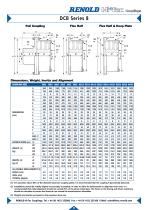
DCB Series 8 Full Coupling Flex Half Flex Half & Keep Plate W2 J2 Dimensions, Weight, Inertia and Alignment COUPLING SIZE COUPLING SIZE A B C D D1 E F G DIMENSIONS J (mm) K L Q R S T U MAX. X MAX. Y MAXIMUM SPEED (rpm) (1) W1 WEIGHT (3) W2 (kg) W3 W4 J1 INERTIA (3) J2 (kg m2) J3 J4 ALLOWABLE MISALIGNMENT (2) RADIAL (mm) AXIAL (mm) CONICAL (degree) (1) For operation above 80% of the declared maximum coupling speed, it is recommended that the coupling is dynamically balanced. (2) Installations should be initially aligned as accurately as possible. In order to allow for deterioration in alignment...
Open the catalog to page 11All RENOLD catalogs and technical brochures
 Corrosion Resistant
6 Pages
 RENOLD SD
8 Pages
 Renold Syno
12 Pages
 Conveyor Brochure
80 Pages
 Transmission - Catalogue
100 Pages
 RENOLD A&S
6 Pages
 General Products
12 Pages
 Renold Roller Chain
4 Pages
 Lifting - Catalogue
24 Pages
 Roll-Ring
8 Pages
 Standard Conveyor
8 Pages
 Renold Klik-Top
4 Pages
 Renold Sovereign
4 Pages
 Spiderjaw & Spiderwrap Couplings
10 Pages
 Chainflex Coupling
14 Pages
 Gearflex Coupling
20 Pages
 UJ Coupling
2 Pages
 RB & PM Catalogue
36 Pages
 Renold Synergy
8 Pages
 PM Series PW Type Wormgear Unit
68 Pages
 jPM Series Wormgear Unit
52 Pages
 Crownpin Couplings
12 Pages
 Pinflex Couplings
14 Pages
 Tyreflex Couplings
12 Pages
 Hydrastart Coupling
22 Pages
 VF Coupling
8 Pages
 MSC catalogue
16 Pages
 Sprag Cage Assemblies
3 Pages
 Universal Joints
28 Pages
 Mill Spindles
20 Pages
 RP Series
76 Pages
 TW Series
44 Pages
 WM Series Wormgear Unit
48 Pages
 Transmission Chain
94 Pages
 Conveyor Chain
80 Pages
 Lifting Chain
24 Pages


Archived catalogs
 Universal Gears Catalogue
846 Pages
- Right angle gearhead
- Compact gearhead
- Shaft shaft coupling
- Gear train gear reducer
- Transmission gearhead
- Shaft gearhead
- Transmission chain
- Helical gear gearhead
- Flange coupling
- Vibration motor
- Clamp gearbox
- Metal chain
- Torque coupling
- Bevel gearhead
- Modular gearhead
- Transfer chain
- Transmission coupling
- Roller chain
- High load capacity gear reducer