Group: MAN

Catalog excerpts

Tooth center distance
Open the catalog to page 1
The production process of the curved tooth couplings was invented by The nominal size of the coupling is no longer synonymouswith the maximum permissible hub bore.Օ Larger hub bore capacities allow a more favorable couplingsize selection. Higher permissible angular misalignment capacity providesadded safety in the event of shaft offset. Օ Precise and subtle size determination due to the applicationof service factors. Re-structured product range ensures simplified couplingselection. Albert Tacke more than 60 years ago andwas already patented in 1939. The worldwide use of the curved tooth...
Open the catalog to page 2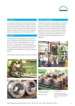
The couplings of the SB series can either be lubricated withoil or with grease. The advantage of oil lubrication is that the lubricant can be replaced in a quicker and easier manner. On top of this, the SB coupling types have a larger space for the lubricant. Lubrication is ensured even in case of a damaged sealing. This equally applies to oil and grease lubrication. Irregardless of the quantity, special designs can be suppliedin any size. The distinction is made between modified stan- dard types and custom-made designs. Modified coupling models are mainly composed of elements from the...
Open the catalog to page 3
Technically complex designՕ Split housing with bolted-on covers Advanced cover design for high misalignment capacity Օ Misalignment capacity of 1.5Ѱper coupling half, for special designsup to 3ѰOptionally available for oil or grease lubrication Օ Low strain on seal rings due to optimum arrangement in the sleevecover Large lubricant space in leak-proof designՕLubrication is ensured, even with damaged seal ring Easy replacement of seal rings Օ Tooth tip centered, optionally available with cover centering Large tooth center distanceՕ Combinable with HYGUARD > safety couplings, brake disks,...
Open the catalog to page 4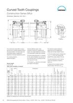
table.main {} tr.row {} td.cell {} div.block {} div.paragraph {}
Open the catalog to page 20
table.main {} tr.row {} td.cell {} div.block {} div.paragraph {}
Open the catalog to page 37
2 fastening screws perplate segment
Open the catalog to page 39
CouplingType Min. SpacerLengthL Oil Quantityfor Oil LubricationGrease Quantityfor Grease Lubrication min min SBL min min min Size per 10 mm tube length with L>L Spacerwith L=L Spacer with L=L per 10 mm tube length with L>L mmlitreslitreskgkg 30 750.0120.00160.0150.002 40 800.0120.00150.0150.0019 50 800.0220.00270.0300.0037 60 1000.0330.00330.0530.0053 70 1000.0380.00380.0580.0058 > min
Open the catalog to page 40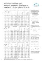
T1 per 10 mm tube length with L>L per 10 mm tube length with L>L Spacer with L=L Spacer withL=L mmNm/radNmmm/radkgm > 2 kgm > 2 kgkg30750.38 10 > 6 186 10 > 6 0.004010.000112.170.1140800.92 10 > per 10 mmtube lengthwith L>L per 10 mm tube length with L>L Spacer with L=L Spacer withL=L min per 10 mm tube length withL>L per 10 mm tube length withL>L Spacer with L=L Spacer withL=L mmNm/radNmmm/radkgm > 2 kgm > 2 kgkg32700.46 >
Open the catalog to page 42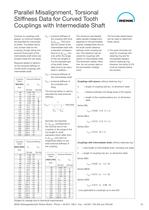
SBG/SRG > T1 C > T2 SizeTorsional StiffnessC > 260235.6 10 > 6 280299.4 10 > 6 300357.3 10 > 6 Calculated acc. to the formula on page 51. 320458.5 10 > 6
Open the catalog to page 43
Fig. 1Fig. 2Fig. 3Fig. 4 Fig. 5Fig. 6Fig. 7Fig. 8 Fig.12345678 Utilization of spaceProductionInsensitiveness to damageOperation quality Axial positioning Transfer of forceInstallation, warmInstallation, cold Removal favorableneutralless favorable RENK Aktiengesellschaft, Rheine Works Phone: +4959717900 Fax: +495971790208and 79025645 >
Open the catalog to page 45
Fig. 1 Fig. 2Fig. 3 Fig. 4 1 Curved tooth coupling with spacerof CFP/ GFP. Flange shaft with gear teeth according to DIN 5480 to takeup axial displacement.2 Curved tooth coupling of verticaldesign for a water power plant,equipped for oil injection lubrication, can be engaged and disengaged at standstill. Gas-nitrided gear teeth. Shiftingdevice with hydraulic cylinder and monitoring sensors.3 Curved tooth coupling with HYGUARD > safety coupling andbrake disk, for vertical installation between motor and thruster. Gas-nitrided gear teeth. 4 Curved tooth coupling with inter-mediate shaft,...
Open the catalog to page 46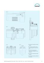
Fig. 5 Fig. 6 Fig. 7 Fig. 8Fig. 9 5 Curved tooth coupling for specialvehicles.6 Curved tooth coupling of short,double engagement constructionform.7 Curved tooth coupling with shear pin part, equipped for flowlubrication. 8 Curved tooth coupling electricallyinsulated.9 Curved tooth coupling coupling forrail vehicles. RENK Aktiengesellschaft, Rheine Works Phone: +4959717900 Fax: +495971790208and 79025647 >
Open the catalog to page 47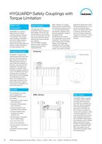
The basic type of the HYGUARD > HYGUARD > ή is a hydraulicsafety element to protectmachinery against overloads. In combination with curved tooth couplings, HYGUARD safety coupling isthe B-design. Due to the com- pact dimensions, this coupling can be combined with the mostdiverse drive elements withoutaffecting their torque transmis- sion capacity. The HYGUARD > works like a safety coupling with torque limitation. Therelease torque is adjustable andremains constant throughout the entire operation time. > ή couplingsleeve is equally suitable for clamping fixed as well as rotating elements....
Open the catalog to page 48
Two components are of essen-tial importance for safe release: the shear ring and the shear tube. The shear ring and theshaft are rigidly connected,whereas the shear tube is accommodated in the movable part. If the operation torque exceeds the pre-determinedvalue, the safety element startsto slide on the profiled surface. This results in a relative move- ment between the shaft andthe hub, with the shear ring cutting off the shear tube. Thesystem is depressurized within milliseconds and the connec- tion is released. HYGUARD > ή HYGUARD > is a versatilemachinery element and suitable for the...
Open the catalog to page 49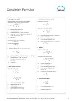
1. Bending Critical Speed 4. Geometrical moment of inertia I Rough calculation of the bending critical speed ofintermediate shafts, spacers and hub sleevesn Applicable to the shaft: > 4 I > axial I > axial = d > k = 300 78.3 E 20.37Applicable to the spacer (tube): G > 4 1 l > n > k = bending critical speed, rpmn= operation speed, rpm E= module of elasticity = 20.6 10 > 4 - d > 4 I > a i axial = d > 4 N/mm > 2 20.37 G > 1 = weight per 1 mm of length, kg/mm (see item 5) l > 4 = tooth center distance, mm I > axial = axial geometrical moment of inertia, mm I > axial = (see item...
Open the catalog to page 51All RENK GmbH catalogs and technical brochures
-
 Gear Units for LNG Carriers
7 Pages
-
 Single Marine Gear Solutions
7 Pages
-
 HYGUARD®Safety Couplings
32 Pages
-
 AX-BO® and RAFINEX®
8 Pages
-
 Bogenzahn-Gelenkspindeln®
12 Pages
-
 HSWL 295
2 Pages
-
 RK 304
2 Pages
-
 Turbo Gear Units
4 Pages
-
 Codad Predator
2 Pages


