- Products
- Catalogs
- News & Trends
- Exhibitions
RLMD01_09
1 /13Pages

RLMD01_09
1 /13Pages
Catalog excerpts

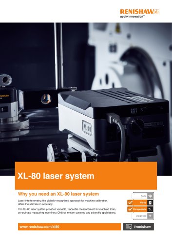
Data sheet RLMD01_09 Issue 9, 14th February 2020 RoLinTM miniature packaged incremental magnetic encoder sensor system RoLinTM is a component level encoder consisting of a RLM readhead and a magnetic scale or ring. It has been designed for embedded motion control applications as a position control loop element. communication protocol is selected the value of internal period counter (1 pole = 1 period) can be output. 8 bit, 12 bit or 24 bit counter lengths can be selected. Optionally, period counter can be reset when traversing the reference mark (if selected). Position information is output in incremental quadrature and parallel, SSI or BiSS format with the option of a periodic reference mark (every pole). When SSI or BiSS failures of the encoder which are signalled on the Error line using a PWM formatted code. ●● Incremental ABZ, TTL or RS422 logic level ●● SSI or BiSS, TTL logic level ●● High speed operation ●● Bidirectional reference mark ●● High reliability from proven nonMaximum speed depends on the contact sensing technology chosen resolution and minimum edge separation time; e.g. for linear ●● Pin / Flex cable options The information carrier is applications to 7 m/s at 1 µm and ●● Self-diagnosis feature a periodically magnetised scale with to 75 m/s at 10 μm. For more a pole length of 2 mm. Radial or information about maximum speed in ●● CE compliant, including RoHS – axial reading of the ring is possible. rotary and linear applications download see Declaration of conformity MR or MS datasheet from RLS media State of the art position sensing center. ensures highly repeatable position measurement under wide installation A self-diagnosis feature enables the tolerances and temperature ranges. sub-system to diag
Open the catalog to page 1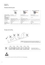
Readhead selection guide RLM with pins RLM with flex cable RLM with RS422 flex cable Mounting bracket Mounting bracket With flex cable and zif connector With flex cable and zif connector Available flex cable output lengths Overall distance to subsequent device Distance depends on loading Distance depends on loading characteristics and edge separation time; characteristics and edge separation time; >50 m (with FPC and extesion cables) generally: <300 mm generally: <300 mm Output type SSI, BiSS-C and Incremental, no line driver (A, B, Z) SSI, BiSS-C and Incremental, no line driver (A, B, Z) Incremental,...
Open the catalog to page 2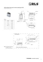
RLM readhead with pins for direct soldering to PCB Dimensions and tolerances are in mm. Reference sensor side Reference mark side Incremental sensor side Note: Hand soldering temperature: Tmax 260 °C; tmax 5 s Flow soldering not allowed. A Without conductive pattern at shaded area
Open the catalog to page 3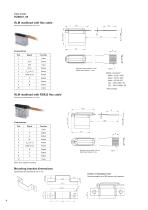
RLM readhead with flex cable Dimensions and tolerances are in mm. Connections Signal Dynamic bend radius: 5 mm Static bend radius: 1 mm Mating connectors*: Molex - 51281-1094 Molex - 52745-1097 Molex - 52746-1071 JST - 10FLH-SM1-TB JST - 10FLH-RSM1-TB * Not provided. RLM readhead with RS422 flex cable Dimensions and tolerances are in mm. Connections Signal Dynamic bend radius: 20 mm Static bend radius: 5 mm Note: Error signal not output Mounting bracket dimensions 5.5 Position of installation holes Recommended use of M2 screws with washers.
Open the catalog to page 4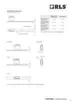
Installation tolerances Dimensions and tolerances are in mm. No back-adhesion tape, with cover foil (option N) No back-adhesion tape (option I) With back-adhesion tape, with cover foil (option B) Scale surface print* With back-adhesion tape (option A) Magnetic scale thickness (A) * For scale surface print description refer to MS01 datasheet. Reference mark side Lateral offset Ride height For radial and axial ring installation tolerances download MR datasheet from RLS media center.
Open the catalog to page 5
Technical specifications System data Maximum length for MS05 scale Pole length System accuracy Linear expansion coefficient for MS scale Better than unit of resolution for movement in the same direction Hand soldering (for pin variant only) Available resolutions and maximum speed for linear applications: Part numbering Maximum count frequency (MHz) Part numbering Minimum edge separation (μs) For rotary maximum speed table refer to MR datasheet from RLS media center. Mechanical data Readhead housing material RLM readhead 1.4 g (without flex), 1.6 g (with flex); magnetic scale MS05 30 g/m; for...
Open the catalog to page 6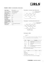
RLM2DE – BiSS-C + Incremental, no line driver Timing diagram – Incremental, unique reference mark Power supply 4.75 V to 5.5 V Reverse polarity protection Current consumption Output signals Rise and fall time (cC = 50 pF) Input signals Permissible MA clock frequency Reference signal 1 or more square-wave pulse Z Edge separation (μs) Resolution (μm) Timing diagram – Incremental, periodic reference mark Edge separation (μs) Resolution (μm) A B Timing diagram – BiSS-C latch position data Period counter value (length depends on the settings chosen)* Position inside the period (length depends on the...
Open the catalog to page 7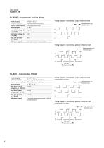
RLM2HD – Incremental, no line driver Power supply 4.75 V to 5.5 V Reverse polarity protection Current consumption Output signals Rise and fall time (cC = 50 pF) Timing diagram – Incremental, unique reference mark Reference signal Edge separation (μs) Resolution (μm) A B 1 or more square-wave pulse Z Timing diagram – Incremental, periodic reference mark Edge separation (μs) Resolution (μm) A B RLM2IC – Incremental, RS422 Timing diagram – Incremental, unique reference mark Power supply 4.75 V to 5.5 V Reverse polarity protection Current consumption Output signals High level output voltage (IOH...
Open the catalog to page 8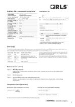
RLM2SJ – SSI + Incremental, no line driver Power supply 4.75 V to 5.5 V Reverse polarity protection Current consumption Output signals Rise and fall time (cC = 50 pF) latch position data Undervoltage; Configuration; System error Permissible MA clock frequency Reference signal 1 or more square-wave pulse Z Amplitude error Input signals Period counter value (length depends on the settings chosen)* Position inside the period (length depends on the resolution) Error data * Optionally, period counter can be reset at the reference mark (options E, F and G - see part numbering on page 10). Error output...
Open the catalog to page 9All RENISHAW catalogs and technical brochures
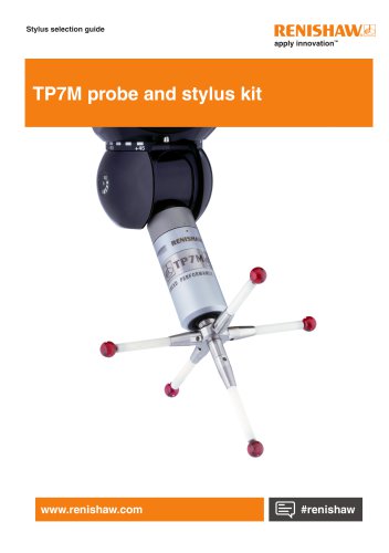 TP7M probe and stylus kit
4 Pages
 inVia Raman microscope
28 Pages
 Renishaw fixtures
68 Pages
 QC20 ballbar
16 Pages
 Precision styli brochure
40 Pages
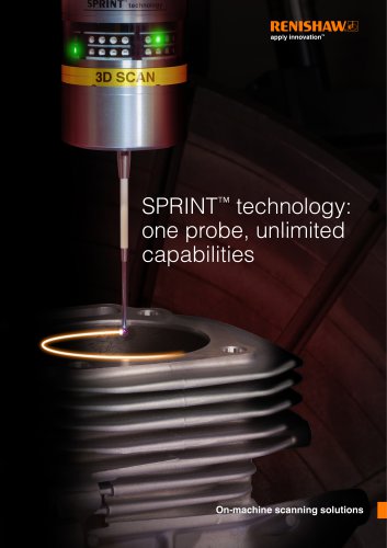 SPRINT technology brochure
11 Pages
 Equator brochure
12 Pages
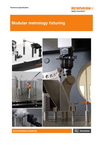
 Metrology fixture table
4 Pages
 RFP1 fringe probe for REVO-2
2 Pages
 RVP vision probe for REVO-2
2 Pages
 MH20 articulating probe head
2 Pages
 Data sheet: MH20 and MH20i
4 Pages
 RTP20
RTP202 Pages
 PH10M-iQ PLUS
2 Pages
 REVO-2 and RSP2 probes
2 Pages
 SFP2 surface finish probe
2 Pages
 Data sheet: HS20 laser head
2 Pages
 Data sheet: RLU20 laser unit
2 Pages
 Data sheet: RLU10 laser unit
2 Pages
 RLBD01_04
9 Pages
 RLCD03_03
9 Pages
 HiLin™
20 Pages
 PRIMO™ system
8 Pages
 RSP3-6 extended reach probe
4 Pages
 RGH25F UHV, RGH20F UHV
8 Pages
 Renishaw retrofit
12 Pages
 SP80
SP804 Pages
 SP600
SP6004 Pages
 Styli for Zeiss applications
57 Pages
 Precision styli
60 Pages
 CMM technology guide
28 Pages


- Temperature probe
- RENISHAW rotary encoder
- Measuring machine
- RENISHAW incremental encoder
- Microscope
- Calibration system
- Spectrometer
- RENISHAW incremental rotary encoder
- Monitoring software solution
- RENISHAW absolute rotary encoder
- Measurement software
- Thermocouple temperature transducer
- Solid-shaft rotary encoder
- Laboratory microscope
- Automated software
- RENISHAW optical rotary encoder
- Programming software
- RENISHAW magnetic rotary encoder
- RENISHAW industrial rotary encoder
- IP67 rotary encoder