- Products
- Catalogs
- News & Trends
- Exhibitions
Commutation and incremental magnetic encoder solutions
1 /19Pages

Commutation and incremental magnetic encoder solutions
1 /19Pages
Catalog excerpts

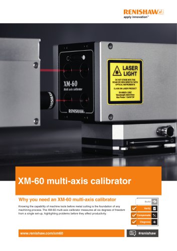
Data sheet UVWD01_01 Issue 1,26th June 2017 RLSCommutation and incremental magnetic encoder solutions Commutation and incremental encoders for motor applications OnAxis™ commutation magnetic rotary encoder range is designed for use in motor feedback applications requiring both A, B, Z incremental and U, V, W commutation signals. Robust non-contact OnAxis sensor technology provides ultimate long term reliability and with simple installation costs of ownership are minimal. Installation is simplified with a range of magnetic actuators and mounting options for the encoder. A simple zero position programming then removes the need for careful alignment of the encoder to starting position of the rotor. Resolutions are available from 64 to 2,048 pulses per revolution (256 to 8,192 counts per revolution with *4 evaluation). U,V,W commutation signals are simultaneously output with 1 to 8 pole pairs (2 to 16 poles). Commutation encoders are available in different design variants and sizes, from 20 mm diameter encoder module RMB20 to 44 mm diameter encoder module on a metal flange RMF44 or as RMC22 and RMC35 on a metal flange with a removable metal cap to allow easy installation and zeroing. The functionality of all the above mentioned encoders is based on the AM4096 magnetic encoder IC which provides reliable operation in tough environments. More on the funcitonalities of AM4096 magnetic encoder IC can be found in AM4096 data sheet. • Robust non-contact OnAxis encoders • Resolutions from 256 to 8192 counts per revolution • U, V, W commutation signals • Encoder module sizes from 20 mm diameter to 44 mm diameter • Operations in tough environments • CE compliant, including RoHS see Declaration of conformity A REIMISHAW.B associate company
Open the catalog to page 1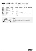
WARNING! ESD protection Encoder modules are ESD sensitive - handle with care. Do not touch electronic circuit or sensor area without proper ESD protection or outside of ESD controlled environment.
Open the catalog to page 2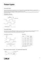
Incremental outputs There are three signals for the incremental output: A, B and Z. Signals A and B are quadrature signals, shifted by 90°, and signal Z is a reference mark. The reference mark signal is produced once per revolution. The width of the Z pulse is 1/4 of the quadrature signal period and it is synchronized with the A and B signals. The position of the reference mark is at zero. The chart below shows the timing diagram of A, B and Z signals with clockwise (CW) rotation of the magnet and positive counting direction. B leads A for CW rotation. Timing diagram - Incremental Complementary...
Open the catalog to page 3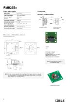
Power supply Power consumption Maximum speed Incremental resolution Commutation outputs Number of poles for commutation outputs Operating temperature Conformal coating type With pads or with Molex connector: mating connector (not provided) Dimensions and installation tolerance Dimensions and tolerances in mm. Connector on board Molex 43045-0810 Mating connector (Not provided) Shell: Molex 43025-0800 8 pin crimp: Molex 43030-0010 zero pads mating connector Zeroing pads NOTE: Product without connector is not conformal coated. magnet actuator NOTE: For the accuracy specified the center line of the...
Open the catalog to page 4
Output specifications Power supply Power consumption Maximum speed Incremental outputs Incremental resolution Commutation outputs Number of poles for commutation outputs Operating temperature –40 °C to +125 °C –40 °C to +105 °C for option 10 (with connector) With pads or with Molex connector: W V U A+ B- Zeroing holes Connector on board Molex 501568-1107 Mating connector (Not provided) Shell: Molex 501330-1100 Crimp terminal: Molex 501334-xxxx Dimensions and installation tolerance Dimensions and tolerances in mm. Component area Clockwise rotation of magnet NOTE: For the accuracy specified the...
Open the catalog to page 5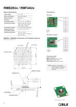
Power supply Power consumption Maximum speed Incremental outputs Incremental resolution Commutation outputs With pads: Number of poles for commutation outputs Operating temperature –40 °C to +125 °C –40 °C to +105 °C for option 12 (with connector) Zeroing pads With Molex connector: PCB RMB28 Component area RMB28Ux / RMB28Wx dimensions and installation tolerance Component area Magnetic actuator Connector on board Molex 501568-1107 Mating connector (Not provided) Shell: Molex 501330-1100 Crimp terminal: Molex 501334-xxxx NOTE: Image may not represent actual product as components can vary based...
Open the catalog to page 6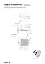
RMF44Ux / RMF44Wx dimensions and installation tolerance Metal flange Component area Component area Clockwise (CW) rotation of magnet
Open the catalog to page 7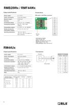
Power consumption 30 mA (not loaded) Incremental outputs A, B, Z, A-, B-, Z- (RS422) commutation outputs Operating temperature -40 °C to +125 °C -40 °Cto +105 °C for option 12 (with connector) Connector on board Molex 501568-1407 Mating connector (Not provided) Shell: Molex 501330-1400 Crimp terminal: Molex 501334-xxxx Power consumption 40 mA (not loaded) Incremental outputs A, B, Z, A-, B-, Z- (RS422) commutation outputs Operating temperature -40 °C to +125 °C Connections Encoder * RM44 with external zeroing is available with binary resolutions only.
Open the catalog to page 8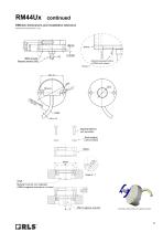
RM44Ux dimensions and installation tolerance RM44 encoder Magnetic actuator RMH Distance between bottom of RM44 and magnet Scale 2:1 Fastener M4×16 (not provided) Tooth washer (not provided) Scale 2 : 1 Shaft Material must be non-magnetic if RMH magnetic actuator is not used Clockwise (CW) rotation of magnet
Open the catalog to page 9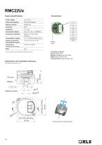
Power supply Power consumption Maximum speed Incremental outputs Incremental resolution Commutation outputs Number of poles for commutation outputs Temperature Operating and storage Zeroing holes Connector on board Molex 501568-1107 Mating connector (Not provided) Shell: Molex 501330-1100 Crimp terminal: Molex 501334-xxxx * At 12 bit resolution and with specified installation tolerances. Dimensions and installation tolerance Magnetic actuator Clockwise rotati
Open the catalog to page 10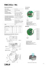
Output specifications Connections Power supply 5 V ± 10 % Power consumption 40 mA (not loaded) Incremental outputs A, B, Z, A-, B-, Z- (RS422) 1,000, 1,024, 1,600, 2,000, 2,048, 4,096, 8,192 cpr Commutation outputs (for Ux) U, V, W (±24 mA output drive) Commutation outputs (for Wx) U, V, W, U-, V-, W- (RS422) commutation outputs Operating temperature -40 °C to +105 °C (Limited by connector. All other components used are specified for operation from -40 °C to +125 °C) Mass 45 g RMC35Ux Resolution options (counts per revolution) W v ~ U ~ A+ ~ A- ~ B- ~ B+ ~ Z+ ~ Z- ~ Vdd (+5...
Open the catalog to page 11All RENISHAW catalogs and technical brochures
 TP7M probe and stylus kit
4 Pages
 inVia Raman microscope
28 Pages
 Renishaw fixtures
68 Pages
 QC20 ballbar
16 Pages
 Precision styli brochure
40 Pages
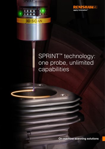 SPRINT technology brochure
11 Pages
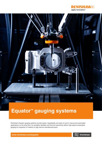 Equator brochure
12 Pages
 Metrology fixture table
4 Pages
 RFP1 fringe probe for REVO-2
2 Pages
 RVP vision probe for REVO-2
2 Pages
 MH20 articulating probe head
2 Pages
 Data sheet: MH20 and MH20i
4 Pages
 RTP20
RTP202 Pages
 PH10M-iQ PLUS
2 Pages
 REVO-2 and RSP2 probes
2 Pages
 SFP2 surface finish probe
2 Pages
 Data sheet: HS20 laser head
2 Pages
 Data sheet: RLU20 laser unit
2 Pages
 Data sheet: RLU10 laser unit
2 Pages
 RLMD01_09
13 Pages
 RLBD01_04
9 Pages
 RLCD03_03
9 Pages
 HiLin™
20 Pages
 PRIMO™ system
8 Pages
 RSP3-6 extended reach probe
4 Pages
 RGH25F UHV, RGH20F UHV
8 Pages
 Renishaw retrofit
12 Pages
 SP80
SP804 Pages
 SP600
SP6004 Pages
 Styli for Zeiss applications
57 Pages
 Precision styli
60 Pages
 CMM technology guide
28 Pages


- Temperature probe
- Measuring machine
- Microscope
- Calibration system
- Spectrometer
- RENISHAW incremental rotary encoder
- Monitoring software solution
- RENISHAW absolute rotary encoder
- Measurement software
- Thermocouple temperature transducer
- Solid-shaft rotary encoder
- Laboratory microscope
- Automated software
- RENISHAW optical rotary encoder
- Programming software
- RENISHAW magnetic rotary encoder
- RENISHAW industrial rotary encoder
- IP67 rotary encoder