MT-W...M
1 /7Pages

MT-W...M
1 /7Pages
Catalog excerpts

MT-W...M time relays • Universal, multifunction time relays with independently controled times T1, T2 and T3 (25 time functions + functions ON and OFF; quick times set with the accuracy of 0,1 s) • Two digit LED display • Programming with two buttons only • Cadmium - free contacts • AC/DC input voltages • Cover - installation module, width 17,5 mm • Direct mounting on 35 mm rail mount acc. to PN-EN 60715 • Application: in low-voltage systems • Compliance with standard PN-EN 61812-1 • Recognitions, certifications, directives: Output circuit - contact data Number and type of contacts Contact material Max. switching voltage Rated load Max. inrush current Rated current Max. breaking capacity Min. breaking capacity Contact resistance Max. operating frequency • at rated load • no load Input circuit 1 CO AgNi 440 V AC / 300 V DC 10 A / 250 V AC 10 A / 24 V DC 16 A 10 A 2 500 VA 0,3 W 5 V, 5 mA 100 m 600 cycles/hour 72 000 cycles/hour Rated voltage AC: 50/60 Hz AC/DC Operating range of supply voltage Rated power consumption AC DC Range of supply frequency AC Residual ripple to DC Control contact S ❶ • min. voltage ❷ • min. time of pulse duration ❷ • max. length of control line Insulation rated voltage Rated surge voltage Overvoltage category Insulation pollution degree Flammability degree Dielectric strength • input - output • contact clearance General data Electrical life • resistive AC1 Mechanical life (cycles) Dimensions (L x W x H) Weight Ambient temperature Cover protection category Environmental protection Relative humidity Shock resistance Vibration resistance • storage • operating type of insulation: basic type of clearance: micro-disconnection ❶ The control terminal S is activated by connection to A1 terminal via the external control contact S. ❷ Where the control signal is recognizable. ❸ Length with 35 mm rail taps: 98,8 mm. PRECAUTIONS: 1. Ensure that the parameters of the product described in its specification provide a safety margin for the appropriate operation of the device or system and never use the product in circumstances which exceed the parameters of the product. 2. Never touch any live parts of the device. 3. Ensure that the product has been connected correctly. An incorrect connection may cause malfunction, excessive heating or risk of fire. 4. In case of any risk of any serious material loss or death or injuries of humans or animals, the devices or systems shall be designed so to equip them with double safety system to guarantee their reliable operation. Export Sales Department phone +48 68 47 90 832, 951 • e-mail: [email protected] Insulation according to PN-EN 60664-1
Open the catalog to page 1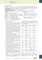
MT-W...M time relays Es, E, E(S), E(r), R, Wu, Wu(S), Wu(r), Ws, Wa, B, Wi, ER, EWs, EWa, EWu, WsWa, EWf, Wt, Pi, Pi(S), Pp, Pp(S), Est, Esp, ON, OFF with two buttons: „F/T” and „OK”, to be with viewed on the LED display 0,1 s ... 99 h 59 min. 59,9 s 0,1 s / 0,12 s temperature: 0,01% / °C supply voltage: 0,1% / V controlled by contact S / supply voltage: 50 ms / 650 ms LED display Selection of function and settings of T1, T2, T3 intervals Timing adjustments Setting accuracy / Repeatability Values affecting the timing adjustment Recovery time LEDs green ”U” - indication of supply voltage U yellow...
Open the catalog to page 2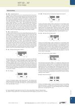
MT-W...M time relays Time functions F0 – OFF - Constant service off. F0 function can be turned on at any time, during feeding the time relay with Un voltage. Turning on F0 function during carrying out any time function will cause the function to stop as well as constant operating relay R off (LED diode ”R” is off). Function F0 is activated by pressing ”F/T” button for a longer time (more than 2 seconds) and selecting F0 function. Confirm this function with red button ”OK” (after confirmation display will show digit 0). Exiting the service function needs a longer pressing of ”F/T” button - until...
Open the catalog to page 3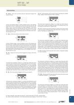
MT-W...M time relays Time functions F6 – Wu(S) - ON for the set interval, with time measurement stopped with contact S closing. Turning on the feeding voltage U causes immediate turning on the operating relay R at the set time T1 (display shows vertical strip spinning to the right, LED diode ”R” is on). If the control contact S is closed, measuring T1 time will be stopped (display shows two horizontal strips) until the moment when control contact is opened. Opening contact S starts further measuring of T1 time. After finishing measuring T1 time the operating relay turns off (display shows ”End”,...
Open the catalog to page 4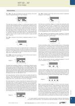
MT-W...M time relays Time functions F13 – EWa - OFF delay and breaking time delay with opening of the control contact S. Independent settings of T1 and T2 intervals. F16 – EWf - ON delay and OFF delay with the control contact S. Independent settings of T1 and T2 intervals. Time relay input is powered by voltage U in a constant way. Closing the control contact S causes immediate turning on the operating relay R (display shows two horizontal strips, and LED diode ”R” is on). Opening the control contact S starts measuring the time T1 (display shows a vertical strip spinning to the right), and after...
Open the catalog to page 5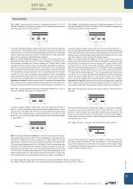
MT-W...M time relays Time functions F18 – Pi(S) - Cyclical operation pulse first. Independent settings of T1 and T2 intervals. Possibility of turninig on or omitting T3 time. Possibility of stopping and resuming cyclic work by control contact S. F19 – Pp(S) - Cyclical operation pause first. Independent settings of T1 and T2 intervals. Possibility of turninig on or omitting T3 time. Possibility of stopping and resuming cyclic work by control contact S. Turning on the feeding voltage U starts cyclic work from turning on the operating relay R for the T1 time (display shows a vertical strip spinning...
Open the catalog to page 6
MT-W...M time relays Dimensions Front panel description Yellow LEDs Green LEDs Connection diagram Relays MT-W...M are designed for direct mounting on 35 mm rail mount acc. to PN-EN 60715. Operational position - any. Connections: max. cross section of the cables: 1 x 2,5 mm2 / 2 x 1,5 mm2 (1 x 14 / 2 x 16 AWG), length of the cable deinsulation: 6,5 mm, max. tightening moment for the terminal: 0,6 Nm. ❶ The control terminal S is activated by connection to A1 terminal via the external control contact S. Two taps: easy assembly on 35 mm rail, firm tapping (top and bottom). Ordering codes Type Number...
Open the catalog to page 7All RELPOL catalogs and technical brochures
 Interface relays
5 Pages
 Catalogue 2021
106 Pages
 Bistable - impulse relays
4 Pages
 High power relays
4 Pages
 Time relays
4 Pages
 Monitoring relays
4 Pages
 Relays for railroad industry
8 Pages
 Solid state relays
4 Pages
 MR-GU1M2P-TR2
4 Pages
 RSR20
RSR204 Pages
 RSR30
RSR305 Pages
 RSR40
RSR403 Pages
 RSR50
RSR5010 Pages
 RLK-1
RLK-12 Pages
 RLK-3
RLK-32 Pages
 Contactors
16 Pages
 RZI60-12-M, RZI60-24-M
3 Pages
 RZI60-24-P
3 Pages
 NEED Programmable Relay
8 Pages
 Signal Lamps
4 Pages
 Time relays
12 Pages
 Relays for electronics
16 Pages
 Relays for industry
16 Pages
 RM12N
RM12N3 Pages
 R2N, R3N, R4N
4 Pages
 R40N
R40N3 Pages
 R30N
R30N3 Pages
 RSM822
3 Pages

Archived catalogs
 Power Supplies
2 Pages
 NEED intelligent relay
8 Pages
 Motor circuit breakers
16 Pages
 Contactors
36 Pages
 Solid State Relays
28 Pages
- Switching relay
- Electromechanical relay
- Time relay
- DC electromechanical relay
- Contactor
- LED indicator light
- Solid state relay
- Monitoring relay
- Power relay
- Printed circuit board electromechanical relay
- Steady pilot light
- DIN rail time relay
- DIN rail monitoring relay
- DC solid state relay
- AC electromechanical relay
- 12VDC electromechanical relay
- DC contactor
- 24VDC electromechanical relay
- Multi-function timer
- Voltage monitoring relay