
Catalog excerpts

Achieving a better part performance, a cleaner working environment and reduced styrene exposure and emissions are major challenges for the composites industry. For that reason the need for improved working processes has been a priority for manufacturers for many years, and has resulted in the development of resin systems with low styrene emissions and low styrene content. RTM Light is one of the processes filling the gap in production volumes between open moulding, like Hand lay up and Spray up (HLU/ SU) and press moulding, like Sheet Moulding Compound (SMC). RTM Light is suitable for small...
Open the catalog to page 2
RTM Light moulding processes are widely used in the composites industry for manufacturing high quality components. These processes typically consist of the following steps: • Preparation of the mould tool (can be with or without a gelcoat) • Placement of reinforcement and/ or core materials in the tool • Tool closure • Resin injection or drawing into the mould • Demoulding of the finished part Resin trap This guide will help to better understand the benefits and limitations of RTM Light processes and allow easier decision making on process parameters
Open the catalog to page 3
RTM Light, also known as Vacuum Assisted Resin Injection (VARI), uses vacuum to draw resin into the mould, while at the same time the resin can be injected under moderate pressure. Vacuum may also be used to clamp the two mould halves. The use of moderate pressures typically means that a less heavy male mould can be used compared with Pressure RTM and SMC moulding processes.
Open the catalog to page 4
Process Overview The process requires a rigid female mould and a semi-rigid male top mould. The mould closure occurs by applying vacuum aided by simple clamping mechanisms. After preparation of the mould (with mould release, optional gelcoat), the reinforcements are applied and the mould is closed with a clamping system. The resin is usually injected at low pressure (max. 1 bar) into a peripheral channel surrounding the part, and vacuum is applied to an exit port near the centre of the part. The low net closing pressure and low internal mechanical forces enable use of lightweight tools. For...
Open the catalog to page 5
Product Selection Considerations When selecting and designing the optimised combination of resin and reinforcement, there are two important parameters to consider: • The end product requirements (mechanical and physical properties) • The process requirements (desire to optimise manufacturing speed, labour, quality and emissions) The overall laminate strength and stiffness are determined by the laminate thickness, the combination of reinforcements and obviously by the resin matrix that holds the reinforcements. Further local strengthening and stiffening may be obtained by using tailored...
Open the catalog to page 6
Resin Selection Laminate mechanical properties are primarily determined by the reinforcement package. Heat resistance, electrical properties, fire retardant properties, and surface quality etc. are mostly determined by the resin system. Also longer term properties, such as water resistance, weathering resistance, heat ageing, fatigue resistance etc. are primarily influenced by the resin system selected. Once the reinforcement package has been selected in line with both the end use and process requirements, the base resin system is selected so that desired short term and long term properties...
Open the catalog to page 7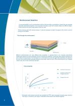
Reinforcement Selection It is recommended to use a reinforcement build-up that provides a combination of good flow and required laminate mechanical properties. If it is required to produce a part with complex design and difficult angles, reinforcements with good drape-ability should be used. When producing part with vertical surfaces, it may be necessary to attach the glass to the mould to avoid it Flow through the reinforcement Resin flow Flow layer Different reinforcements can have different flow properties. In general there is an inversely proportional relationship between the flow...
Open the catalog to page 8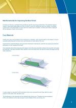
Reinforcements for Improving Surface Finish Asurface veil, tissue or synthetic felt is sometimes used for improving surface finish. The selected material needs to have good drape-ability and flow in order to avoid air entrapment near the surface. A synthetic surface layer is recommended if a more resin rich surface layer is desired, or when parts without a gelcoat will be exposed to harsh environments. Core Materials Inserts and cores can be placed in the mould prior to injection. Care must be taken in the design to ensure accurate positioning and to ensure even part thickness on both sides...
Open the catalog to page 9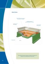
Mould Setup Channel to feed resin by vacuum or light pressure or combination Lightweight upper mould (typically transparent FRP laminate) Support frame for easy handling Vacuum clamping seals and ports The RTM Light method is typically considered cost effective for production of 50-1500 parts per tool per year.
Open the catalog to page 10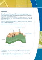
Mould Details The use of vacuum for mould filling, means that RTM light moulds are subjected to relatively low pressures. For that reason they can be constructed lighter and less rigid in comparison with moulds used for Pressure RTM or for SMC moulding processes. However similar design principles still apply. Also the moulds must be robust enough to withstand production handling. A RTM Light tool typically consists of a relatively stiff under mould (standard FRP mould, produced with Polylite® Profile Tooling system), and a semi-rigid, transparent, upper mould (typically produced with a high...
Open the catalog to page 11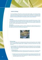
Injection Strategy One of the challenges in RTM Light is to choose the right 'injection strategy'. This includes parameters such as where to place the injection/ vacuum points and the choice of reinforcement. The placement of the injection point must be carefully decided and is usually located at the furthest point. The geometrical centre is a good first choice for evaluating injection point options. For larger or more complex parts several injection points can be considered with the object of reducing filling time and avoiding air-entrapment. Good seals The closing vacuum seals must be...
Open the catalog to page 12All Reichhold catalogs and technical brochures
-
 UROTUF® F275-M-75
2 Pages
-
 EPOTUF® 38-698
2 Pages
-
 F600-W-40
2 Pages
-
 UROTUF®
7 Pages
-
 DION® IMPACT 9133
2 Pages
-
 UROTUF® Water-borne Urethane
4 Pages
-
 BioiPreferred® Guideline
2 Pages
-
 NORPOL® ULTIMATE GELCOAT
2 Pages
-
 NORPOL® SVX Gelcoat
2 Pages
-
 NORPOL® SVG Gelcoats
3 Pages
-
 NEW NORPOL® SRG GELCOAT
2 Pages
-
 DION® Corrosion Guide
45 Pages
-
 POLYLITE ® 3354225
3 Pages
-
 EPOTUF® 38-698
2 Pages
-
 Improved vinyl ester technology
21 Pages
-
 UROTUF® F600-W-40
2 Pages
-
 UROTUF® E300-W-40
2 Pages
-
 Corrosion Guide
45 Pages
-
 Coating Resins Catalog
35 Pages
-
 BECKOSOL AQ®
12 Pages
-
 AROFLINT® Flyer
2 Pages
-
 Material Selection Guide
77 Pages
-
 FRP Inspection Guide
36 Pages
-
 Vacuum Foil Infusion
19 Pages
-
 Pultrusion (Europe)
3 Pages
-
 A Reichhold Company Overview
11 Pages
-
 NORPOL® VBC Barriercoat
3 Pages
-
 NORPOL® GI
3 Pages
-
 NORPOL® CPG
4 Pages
-
 Pultrusion (EMEA)
3 Pages
-
 NORPOL® SVG Gelcoats
4 Pages
-
 Fire Retardant (EMEA)
15 Pages
-
 Bonding Paste (EMEA)
15 Pages


Archived catalogs
-
 Vacuum Foil/ RTM Process (EMEA)
11 Pages
-
 Tooling System (EMEA)
11 Pages
-
 SMC/ BMC (EMEA)
3 Pages