Catalog excerpts

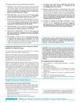
ECII® Safety Warning — LP-Gas Pressure Relief Valves Purpose In its continuing quest for safety, Engineered Controls International, Inc. is publishing safety warning bulletins explaining the hazards associated with the use, misuse and aging of ECII®/ RegO® Products. LP-Gas dealer managers and service personnel must realize that the failure to exercise the utmost care and attention in the installation, inspection and maintenance of these products can result in personal injury and property damage. The National Fire Protection Association Pamphlet #58 “Storage and Handling of Liquefied Petroleum Gases” states: “In the interests of safety, all persons employed in handling LP-Gases shall be trained in proper handling and operating procedures.” ECII® Warning Bulletins are useful in training new employees and reminding older employees of potential hazards. This Warning Bulletin should be provided to all purchasers of ECII® / RegO® Products and all personnel using or servicing these products. Additional copies are available from Engineered Controls International, Inc. and your Authorized ECII®/ RegO® Products Distributor. What You Must Do: • Read This Entire Warning • Install Properly • Inspect Regularly Scope This bulletin applies to pressure relief valves installed on stationary, portable and cargo containers and piping systems utilized with these containers. This bulletin is not intended to be an exhaustive treatment of this subject and does not cover all safety practices that should be followed in the installation and maintenance of LPGas systems. Each LP-Gas employee should be provided with a copy of NPGA Safety Pamphlet 306 “LP-Gas Regulator and Valve Inspection and Maintenance” as well as the NPGA “LP-Gas Training Guidebooks” relating to this subject. Warnings should be as brief as possible. If there is a simple warning, it is: Install Properly Pipeaways and deflectors may be required by local codes, laws and regulations depending on the installation. Use only ECII®/ RegO ® adapters on ECII®/ RegO® relief valves. Adapters not designed specifically for piping away ECII®/ RegO® relief valves, such as those with 90° turns or reduced internal diameters, will decrease flow dramatically. These should never be used as they can cause the relief valve to chatter and eventually destroy itself. Consult NFPA Pamphlet #58 and/or any applicable regulations governing the application and use of pressure relief valves. Make sure you are thoroughly trained before you attempt any valve installation, inspection or maintenance. Proper installation is essential to the safe operation of pressure relief valves. When installing ECII®/ RegO® pressure relief valves, consult warning # 8545-500 which accompanies each valve. Check for damage and proper operation after valve installation. Check that the valve is clean and free of foreign material. Inspect Regularly A pressure relief valve discharges when some extraordinary circumstance causes an over pressure condition in the container. If a pressure relief valve is known to have discharged, the relief valve, as well as the entire system, should be immediately and thoroughly inspected to determine the reason for the discharge. In the case of discharge due to fire, the valve should be removed from service and replaced. Inspect pressure relief valves regularly. Replace unsafe or suspect valves immediately. Use common sense. The addition of deflectors, pipeaway adapters and piping will restrict the flow. To properly protect any container, the total system flow must be sufficient to relieve pressure at the pressure setting of the relief valve in accordance with all applicable codes. Relief valves should be inspected each time the container is filled but no less than once a year. If there is any doubt about the condition of the valve, it must be replaced. Eye protection must be worn when performing inspection on relief valves under pressure. Never look directly into a relief valve under pressure or place any part of your body where the relief valve discharge could impact it. In some cases a flashlight and a small mirror are suggested to assist when making visual inspections. Pressur Relief Valves & Relief Valve Manifolds e 37
Open the catalog to page 1
To Properly Inspect A Pressure Relief Valve, Check For: 1. A rain cap. Check protective cap located in valve or at end of pipeaway for a secure fit. Protective caps help protect the relief valve against possible malfunction caused by rain, sleet, snow, ice, sand, dirt , pebbles, insects, other debris and contamination. REPLACE DAMAGED OR MISSING CAPS AT ONCE AND KEEP A CAP IN PLACE AT ALL TIMES. 2. Open weep holes. Dirt, ice, paint and other foreign particles can prevent proper drainage from the valve body. IF THE WEEP HOLES CANNOT BE CLEARED, REPLACE THE VALVE. 3. Deterioration and...
Open the catalog to page 2
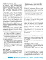
Operation of Pressure Relief Valves Pressure relief valves are set and sealed by the manufacturer to function at a specific “start-to-discharge” pressure in accordance with regulations. This set pressure, marked on the relief valve, depends on the design requirement of the container to be protected by the relief valve. If the container pressure reaches the start-to-discharge pressure, the relief valve will open a slight amount as the seat disc begins to move slightly away from the seat. If the pressure continues to rise despite the initial discharge through the relief valve, the seat disc...
Open the catalog to page 3
Chart A — Minimum Required Rate of Discharge for LP-Gas Pressure Relief Valves Used on Minimum required rate of discharge in cubic feet per minute of air at 120% of the maximum permitted start-to-discharge ASME Containers pressure for pressure relief valves to be used on containers other than those constructed in accordance with Interstate From NFPA Pamphlet #58, Appendix D (1986). Commerce Commission specification. Surface Area Sq. Ft. Surface area =Total outside surface area of container in square feet. When the surface area is not stamped on the name plate or when the marking is not...
Open the catalog to page 4All Rego Europe catalogs and technical brochures
-
A60 series
4 Pages
-
A85 series
1 Pages
-
7572C-14C
1 Pages
-
globe angle valve
9 Pages
-
relief valves
2 Pages
-
adapters
6 Pages
-
RegO®
1 Pages
-
Flow Controls
24 Pages
-
GODDARD catalogue
40 Pages
-
REGO L-102 Catalogue
96 Pages
-
CG400 - CRYO-FLOW Products
43 Pages


