- Catalogs
- Reece Safety Products
- Power Protection Seal

Power Protection Seal

Power Protection Seal
Product Overview
The document provides technical data and assembly instructions for the Power Protection Seal PPS11, produced by Reece Safety Products Ltd. It includes product information essential for correct installation and use.
Company Information
Reece Safety Products Ltd is located at Unit B9, Lowfields Close, Lowfields Business Park, Elland, West Yorkshire HX5 9DX. Contact details include telephone: 01422 310456, fax: 01422 311070, and email: [email protected]. Their website is www.reecesafety.co.uk.
Document Structure
The technical data sheet is divided into two sheets (1A and 1B), both dated March 2017. The sheets contain product specifications, assembly instructions, and preparation steps for the Power Protection Seal PPS11.
Key Sections
- Product Specifications: Details about the Power Protection Seal PPS11, including its intended use with sockets and power protection.
- Assembly Instructions: Step-by-step guidance on how to prepare and assemble the seal correctly to ensure safety and functionality.
- Preparation: Initial steps required before assembly, ensuring the product is ready for installation.
Critical Information
The document emphasizes the importance of following the assembly instructions carefully to maintain product integrity and safety. Contact information is provided for technical support or further inquiries.
Catalog excerpts
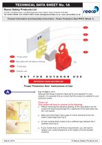
SUITABILITY Although the Power Protection Seal will fit most standard 13 amp sockets, it is essential that you check that this product is suitable for your particular socket. Check List Your socket will have to conform to the following: • Without removing the adhesive backing, fit the back plate over the socket and insert plug through the 3 apertures of the back plate into the 3-pin socket • Make sure that Edge A has a gap of 2.0mm (minimum) from the switch inside edge (see Fig 2) • On twin sockets there needs to be a sufficient gap between the 2 switches (see Fig 2). • If your socket does not fit these requirements, you will need to replace your socket (telephone us for details of recommended socket/s). © Reece Safety Products Ltd
Open the catalog to page 1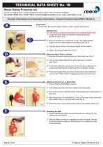
Preparation 1/ Ensure that the surface of the socket is clean, grease free and dry Marking Out Do not remove adhesive backing when completing this task 1/ Locate the back plate on socket by inserting plug into apertures (see Fig 3) 21 Ensure that there is a minimum of a 2.0 mm gap between Edge A and the inside edge of the switch (see Fig 3) 3/ Using a pencil, mark a line along Edge A on the socket 4/ Mark a line along Edge B (se Fig 3) Attaching Back Plate to Socket 1/ Remove adhesive backing sheet on back plate (see Fig 4) 2/ Line up back plate Edge A & B with guide line on socket (see Fig 5) 3/...
Open the catalog to page 2All Reece Safety Products catalogs and technical brochures
 60kV Rescue Hook
1 Page
 ELE09 Switchboard Matting
4 Pages
 Lockable plug covers
1 Page
 Plug Block
1 Page
 Full 2015/16 Catalogue
100 Pages
 Electrical Safety Boots
1 Page
 Electrical Safety Gloves
1 Page
 RSPL1 Plug Lockout
1 Page
 ECBKIT MCB Lockout Kit
2 Pages
 Pneumatic Lockouts
1 Page
 Plug Lockouts
1 Page
 BS18 Cable Lockout
1 Page
 CB15 Breaker Blocker Kit
1 Page
 Fuse Lock / Blockouts
1 Page
 IEC 60320 Lockout
1 Page
 LP550 Plug Lockouts
1 Page
 Power Protection Seal
2 Pages