- Catalogs
- Reece Safety Products
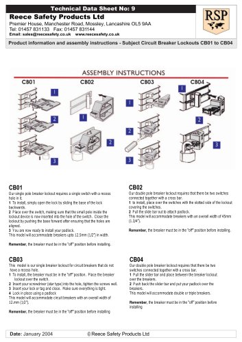
- CB09 to CB11 MCB Lockouts

CB09 to CB11 MCB Lockouts
CB09 to CB11 MCB Lockouts
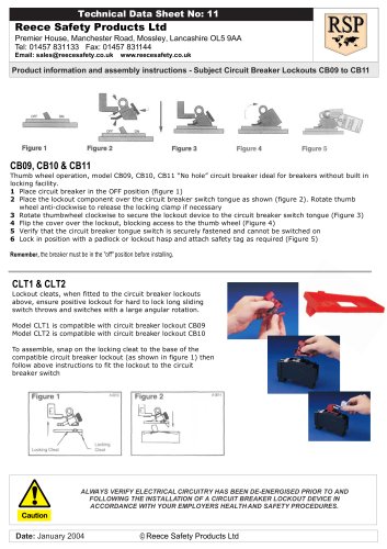
- Ensure the circuit breaker is in the OFF position.
- Place the lockout component over the circuit breaker switch tongue.
- Rotate the thumb wheel clockwise to secure the lockout device.
- Flip the cover over the lockout to block access to the thumb wheel.
- Verify the circuit breaker switch is securely fastened.
- Lock the device with a padlock or lockout hasp and attach a safety tag as needed.
Catalog excerpts
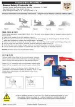
Reece Safety Products Ltd Premier House, Manchester Road, Mossley, Lancashire OL5 9AA Tel: 01457 831133 Fax: 01457 831144 Email: [email protected] www.reecesafety.co.uk Product information and assembly instructions - Subject Circuit Breaker Lockouts CB09 to CB11 Technical Data Sheet No: 11 Date: January 2004 © Reece Safety Products Ltd CB09, CB10 & CB11 Thumb wheel operation, model CB09, CB10, CB11 “No hole” circuit breaker ideal for breakers without built in locking facility. 1 Place circuit breaker in the OFF position (figure 1) 2 Place the lockout component over the circuit breaker switch tongue as shown (figure 2). Rotate thumb wheel anti-clockwise to release the locking clamp if necessary 3 Rotate thumbwheel clockwise to secure the lockout device to the circuit breaker switch tongue (Figure 3) 4 Flip the cover over the lockout, blocking access to the thumb wheel (Figure 4) 5 Verify that the circuit breaker tongue switch is securely fastened and cannot be switched on 6 Lock in position with a padlock or lockout hasp and attach safety tag as required (Figure 5) Remember, the breaker must be in the “off” position before installing. ALWAYS VERIFY ELECTRICAL CIRCUITRY HAS BEEN DE-ENERGISED PRIOR TO AND FOLLOWING THE INSTALLATION OF A CIRCUIT BREAKER LOCKOUT DEVICE IN ACCORDANCE WITH YOUR EMPLOYERS HEALTH AND SAFETY PROCEDURES. CLT1 & CLT2 Lockout cleats, when fitted to the circuit breaker lockouts above, ensure positive lockout for hard to lock long sliding switch throws and switches with a large angular rotation. Model CLT1 is compatible with circuit breaker lockout CB09 Model CLT2 is compatible with circuit breaker lockout CB10 To assemble, snap on the locking cleat to the base of the compatible circuit breaker lockout (as shown in figure 1) then follow above instructions to fit the lockout to the circuit breaker switch
Open the catalog to page 1All Reece Safety Products catalogs and technical brochures
 Power Protection Seal
2 Pages
 60kV Rescue Hook
1 Page
 ELE09 Switchboard Matting
4 Pages
 Lockable plug covers
1 Page
 Plug Block
1 Page
 Full 2015/16 Catalogue
100 Pages
 Electrical Safety Boots
1 Page
 Electrical Safety Gloves
1 Page
 RSPL1 Plug Lockout
1 Page
 ECBKIT MCB Lockout Kit
2 Pages
 Pneumatic Lockouts
1 Page
 Plug Lockouts
1 Page
 BS18 Cable Lockout
1 Page
 CB15 Breaker Blocker Kit
1 Page
 Fuse Lock / Blockouts
1 Page
 IEC 60320 Lockout
1 Page
 LP550 Plug Lockouts
1 Page
 Power Protection Seal
2 Pages