- Catalogs
- Reece Safety Products
- BS07, BS08 Ball Valve Lockouts

BS07, BS08 Ball Valve Lockouts

BS07, BS08 Ball Valve Lockouts
- Compress the handwheel knob to open the clamp.
- Place the lockout on the valve handle.
- Rotate the lockout arm against the pipe in the direction of valve rotation.
- Turn the handwheel clockwise to tighten the clamp against the valve handle.
- Insert a padlock into the locking cleat assembly.
- Verify all associated hazardous energy is de-energized before and after installation.
- Appropriate use of the lockout product is the user's responsibility in compliance with Health and Safety Regulations.
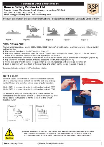
- Turn the valve handle to the off or closed position.
- Slip the lockout device onto the valve handle as far as possible.
- Position the lockout device tab over the angled portion of the valve handle.
- Squeeze the valve handle and lockout device together, inserting a lock into the hole for the tightest fit.
- Ensure the tab is against the valve handle and the lower paddle touches the valve body or pipe.
- Proper installation should prevent the valve from moving toward the open position.
Catalog excerpts

Reece Safety Products Ltd Premier House, Manchester Road, Mossley, Lancashire OL5 9AA Tel: 01457 831133 Fax: 01457 831144 Email: [email protected] www.reecesafety.co.uk Product information and assembly instructions - Subject Settable Ball Valve Lockout Technical Data Sheet No: 6 1 Compress the handwheel knob to open clamp (Fig. 1) 2 Place the Ball Valve Lockout on the valve handle (Fig.2) 3 Rotate the Ball Valve Lockout arm against the pipe in the direction of the valve rotation. (Fig. 3) 4 Turn the handwheel clockwise to tighten the clamp against the valve handle. (Fig. 4) 5 Place padlock in the locking cleat assembly. Notes: When using additional locking arms (BS05A and BS06A) with Models BS05 and BS06 Ball Valve Lockouts, before assembling onto the valve, completely unscrew the handwheel assembly and place the additional locking arm onto the rising stem. Replace the handwheel assembly and turn the handwheel clockwise to clamp down the spring. Then follow instructions shown above and use the secondary arm to lock the valve in the required position. Date: March 2007 © Reece Safety Products Ltd WARNING!! ! All associated hazardous energy should be verified as de-energized prior to and following the installation of a Lockout device. ! Appropriate use of the Lockout product is the sole responsibility of the user in relation to compliance of employers and current Health and Safety Regulations. 1. Turn valve handle to off or closed position (Fig. 1) 2. Slip Lockout Device onto valve handle as far as possible (Fig. 1). 3. Position Lockout Device tab over angled portion of valve handle (Fig. 2) 4. Squeeze valve handle and Lockout Device together and insert lock into hole that provides tightest fit. Make sure tab is against valve handle and lower paddle is touching valve body or pipe (Fig. 3) 5. When properly installed valve should not move toward open position. Product information and assembly instructions - Subject Slide on Ball Valve Lockouts NOTICE: This Lockout Device is designed to prevent inadvertent or accidental energization of a quarterturn type ball valve. Fig 1 Fig 2 Fig 3 Fig 4
Open the catalog to page 1All Reece Safety Products catalogs and technical brochures
 Power Protection Seal
2 Pages
 60kV Rescue Hook
1 Page
 ELE09 Switchboard Matting
4 Pages
 Lockable plug covers
1 Page
 Plug Block
1 Page
 Full 2015/16 Catalogue
100 Pages
 Electrical Safety Boots
1 Page
 Electrical Safety Gloves
1 Page
 RSPL1 Plug Lockout
1 Page
 ECBKIT MCB Lockout Kit
2 Pages
 Pneumatic Lockouts
1 Page
 Plug Lockouts
1 Page
 BS18 Cable Lockout
1 Page
 CB15 Breaker Blocker Kit
1 Page
 Fuse Lock / Blockouts
1 Page
 IEC 60320 Lockout
1 Page
 LP550 Plug Lockouts
1 Page
 Power Protection Seal
2 Pages