- Catalogs
- Reece Safety Products
- BS01, BS02, BS03 Ball Valve Lockouts
BS01, BS02, BS03 Ball Valve Lockouts
1 /1Page

BS01, BS02, BS03 Ball Valve Lockouts
1 /1Page
Catalog excerpts

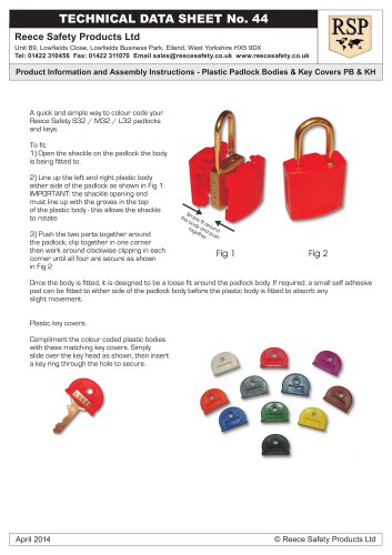
Reece Safety Products Ltd Premier House, Manchester Road, Mossley, Lancashire OL5 9AA Tel: 01457 831133 Fax: 01457 831144 Email: [email protected] www.reecesafety.co.uk Product information and assembly instructions - Subject B-Safe Ball Valve Lockouts Technical Data Sheet No: 3 DESCRIPTION Design Ball valve lockout, Models BS01 & BS02 allow valves to be locked in either the open or closed positions. Model BS03 locks closed only Features Fully dielectric, good low-temperature resistance Material Intermediate-Impact Polypropylene Copolymer Flash Point 330 deg. C Dielectric Constant 2.3 to 2.4 Process Injection molding Colour Available in Red, Yellow, Blue and Green UV Protection Provided by the colour added to the base resin DIMENSIONS CHEMICAL RESISTANCE Polypropylene like most of the polyolefins, is highly resistant to solvents, chemicals and most strong mineral acids and bases but it is subject to attack by oxidizing agents such as chlorosulfonic acids, oleum, sulfuric acid, hydrogen peroxide (at 210 F), sulfuric acid (at 140 F), fuming nitric acid, liquid bromine, etc. With a few exceptions, however, inorganic chemicals produce little or no effect on our products over a period of 6 months at temperatures up to 250 F. When the product is removed from an organic chemicals environment such as benzene, carbon tetrachloride, petroleum, ethanol, acetone, etc. evaporation will take place and changes resulting from the absorption will be reversed if evaporation is complete. USEFUL SERVICE LIFE The useful service life expectancy is 4 years and is limited by the nature of the environment. Date: March 2007 © Reece Safety Products Ltd ASSEMBLY INSTRUCTIONS PARTS 1 VALVE HANDLE COVER 2 MULTIPLE LOCKOUT SLIDING PIECE 3 SLIDING ADJUSTMENT PIECE 4 FRONT EXTENSION INSTALLATION Cover valve handle with part 1. If need be (for larger ball valves 2” 3”) slide part 4 into front of part 1. For maximum adjustment, insert part 3 either recto or verso depending on the thickness of the valve handle.Slide part 2 over part 1. Align holes and install your lock. ASSEMBLY INSTRUCTIONS PARTS 1 VALVE HANDLE COVER 2 MULTIPLE LOCKOUT SLIDING PIECE 3 SLIDING ADJUSTMENT PIECE INSTALLATION Cover valve handle with part 1. For maximum adjustment insert piece 3 either recto or verso depending on the thickness of valve handle. Slide part 2 over part 1. Align holes and install your lock. ASSEMBLY INSTRUCTIONS ASSEMBLY INSTRUCTIONS PARTS 1 VALVE HANDLE COVER 2 MULTIPLE LOCKOUT SLIDING PIECE INSTALLATION Cover valve with part 1. Slide part 2 over part 1. Align holes and install your lock. N/B The valve cannot be locked in the open position with the BS03 BS01 BS02 BS03
Open the catalog to page 1All Reece Safety Products catalogs and technical brochures
 Power Protection Seal
2 Pages
 60kV Rescue Hook
1 Page
 ELE09 Switchboard Matting
4 Pages
 Lockable plug covers
1 Page
 Plug Block
1 Page
 Full 2015/16 Catalogue
100 Pages
 Electrical Safety Boots
1 Page
 Electrical Safety Gloves
1 Page
 RSPL1 Plug Lockout
1 Page
 ECBKIT MCB Lockout Kit
2 Pages
 Pneumatic Lockouts
1 Page
 Plug Lockouts
1 Page
 BS18 Cable Lockout
1 Page
 CB15 Breaker Blocker Kit
1 Page
 Fuse Lock / Blockouts
1 Page
 IEC 60320 Lockout
1 Page
 LP550 Plug Lockouts
1 Page
 Power Protection Seal
2 Pages