
Catalog excerpts

1 ! DIFFERENCE (A-B), OR DRAW [(A-B)/B] INDICATION ! 6-DIGIT, 0.56" (14.2 mm) HIGH LED DISPLAY WITH NEGATIVE SIGN, OVERFLOW & DISPLAYED VALUE INDICATORS ! THREE SEPARATELY DISPLAYABLE VALUES: A, B, & C ! TWO PRESETS ASSIGNABLE TO A, B, OR C ! SEPARATE INPUT SCALING FOR BOTH RATE A & B CHANNELS ! ACCEPTS COUNT RATES TO 10 KHz ! SOLID-STATE CURRENT SINK OUTPUTS ! OPTIONAL 20 mA CURRENT LOOP FOR SERIAL DATA COMMUNICATION ! OPTIONAL RELAY OUTPUTS (Field Replaceable) ! PROGRAMMABILITY OF DECIMAL POINT LOCATION & LEADING ZERO BLANKING ! PROGRAMMABLE TIMED OUTPUTS (0.01 TO 599.99 sec.) ! ABILITY TO LOCK OUT FRONT PANEL FUNCTIONS ! SEALED FRONT PANEL CONSTRUCTION (NEMA 4/IP65) ! NON-VOLATILE MEMORY (E2PROM) DESCRIPTION The Gemini 5200 is a multifunction dual rate indicator which can fulfill almost any rate indication application. The unit can operate as two independent rate indicators, with scaling, decimal point placement, and update times separately programmable for each channel. The Gemini 5200 also has three other unit personalities. These personalities feature a third display Channel C, which can indicate the ratio, difference or draw between the A and B rate channels. The programming of the rate channels and the calculated display is a very straightforward task. Setting up Channel C only requires programming the desired amount of resolution (for ratio and draw) and the appropriate decimal point location. The Gemini 5200 simply takes the two rate values and mathematically calculates display “C” accordingly. The rate indicators use a time interval method (1/tau) to calculate the rate value. This method enables high resolution at all input rates. The unit counts input pulses and after a programmable minimum update time has occurred, it waits until the next count edge occurs, then takes the elapsed time and number of edges and calculates the rate value. At slower rates, averaging can be accomplished by programming the “Rate Minimum Update Time” (0.5 sec. to 16 sec.) for the desired response. The minimum input frequency is 0.03 counts/sec. or one pulse every 32 sec. Extensive scaling capabilities allow practically any desired reading at very slow input rates. The 20 mA Current Loop Communications Option provides the capability of two-way serial communications between the Gemini and other equipment such as a printer, programmable controller, or host computer. The baud rate can be set to 300, 600, 1200, or 2400 baud. The format for transmitted and received data is 1 start bit, 7 data bits, 1 parity bit (odd), and a stop bit. When utilizing an external power supply (30 VDC max.), up to sixteen units can be installed in the loop, each with an individual address. When utilizing the Gemini’s 20 mA current source, up to seven units can be installed in a loop. The Rate values, Presets, and Scale Factors can all be interrogated, while the Presets and Scale Factors can also be changed by sending the proper command codes and numerical data. Various “Print Options” can be selected to automatically interrogate the Rate values, Presets, or Scale Factors by activating the “Print Request” terminal when a printer is being used. The construction of the Gemini 5200 features a metal die-cast bezel, offering maximum durability with a high quality appearance. The sealed front panel meets NEMA 4/IP65 specifications for wash-down and/or dust when properly installed. Electrical connections are made via plug-in terminal strips. Clamptype pressure plate terminals accept stripped #14 AWG wire without lugs. SPECIFICATIONS 1. DISPLAY: 6-digit 0.56" (14.2 mm) High LED display. 2. POWER REQUIREMENTS: AC Power: Switch selectable 115/230 VAC (±10%), 50/60 Hz, 20 VA DC Power: 11 to 14 VDC @ 0.7 A max. 3. SENSOR POWER: +12 VDC (±25%) @ 100 mA. 4. MEMORY: Non-volatile E2PROM memory retains all programming information when power is removed or interrupted. Power Cycles (ON/OFF): 100,000 min. Data Retention: 10 years min. 5. INPUTS A AND B: Switch selectable to accept pulses from a variety of sources including switch contacts, outputs from CMOS or TTL circuits, and all standard RLC sensors. Current Sourcing: Unit provides 3.9 KÙ pull-down resistor for sensors with current sourcing outputs. (Max. input voltage = 28 VDC @ 7 mA.) Current Sinking: Unit provides 7.8 KÙ pull-up resistor for sensors with current sinking outputs. (Max. sensor current = 1.6 mA.) Debounce: Damping capacitor provided for switch contact debounce. Limits rate to 100 Hz max. with 50% duty cycle. Lo Bias: Input trigger levels VIL = 1.5 V, VIH = 3.75 V Hi Bias: Input trigger levels VIL = 5.5 V, VIH = 7.5 V Note: Bias levels given are ±10% @ 12 VDC. They vary proportionally with sensor supply voltage at “DC OUT” terminal. 6. MAGNETIC PICKUP INPUTS A & B: Sensitivity: 150 mV peak (typical @ 12 VDC) Hysteresis: 100 mV Input Impedance: 26.5 KÙ @ 60 Hz Maximum Input Voltage: ±50 Vp GEMINI 5200 - PRESETTABLE DUAL RATE INDICATOR WITH RATIO (A/B) DIMENSIONS In inches (mm) Note: Recommended minimum clearance (behind the panel) for mounting clip installation is 6.8" (173) W. Bulletin No. GEM5-C Drawing No. LP0321 Released 1/05 Tel +1 (717) 767-6511 Fax +1 (717) 764-0839 www.redlion.net
Open the catalog to page 1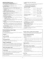
2 SPECIFICATIONS (Cont’d) 7. RATE ACCURACY AND REPEATABILITY: +0.025% 8. RATE MINIMUM INPUT FREQUENCY: 0.03 Hz Note: At frequencies below 0.03 Hz (1 pulse every 32 sec.) the rate indicator will display a zero. 9. RATE MAXIMUM INPUT FREQUENCY: 10 KHz 10. CONTROL INPUTS: Reset: Active low (VIL = 1.5 V max.) internally pulled up to +12 VDC (ISNK = 3 mA), Activation and De-activation response time = 10 msec. Program Disable: Active low (VIL = 1.5 V max.), internally pulled up to +5 VDC (ISNK = 1 mA). Print Request: (GEM521xx only) Active low (VIL = 1.5 V max.), internally pulled up to +5 VDC...
Open the catalog to page 2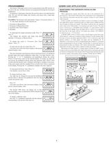
3 PROGRAMMING The Gemini 5200 input circuit set-up is programmed using DIP switches on the rear of the unit. All other functions are programmed through the front panel pushbuttons. To program or interrogate a function, the user first enters a two-digit function code. The unit will then display that function code along with a single-digit mode identifier. EXAMPLE: The function code representing “Output 1 Termination Modes” is 52. The mode identifiers for this function are: 3. Terminate at Manual Reset 4. Terminate at Manual Reset End 5. Terminate after Timed Output 1 6. Boundary To...
Open the catalog to page 3All Red Lion Controls catalogs and technical brochures
-
 FlexEdge Water/Wastewater
4 Pages
-
 FlexEdge Oil & Gas
12 Pages
-
 FlexEdge Brochure
8 Pages
-
 Graphite® Expansion Racks
3 Pages
-
 Graphite® Core Controller
2 Pages
-
 PXU PID Controller
3 Pages
-
 PAX® 2C PID Controller
3 Pages
-
 E3 I/O™ Modules
3 Pages
-
 Graphite® Edge Controller
2 Pages
-
 CR1000 and CR3000
4 Pages
-
 NT24k-16M12
4 Pages
-
 RAM-6000 3G
3 Pages
-
 SN-6000 3G Data Sheet
3 Pages
-
 NTPS-24-1.3 Power Supply
1 Pages
-
 Modular Controller Brochure
8 Pages
-
 HMI Brochure
18 Pages
-
 Data Station Plus Brochure
8 Pages
-
 Protocol Sell Sheet
2 Pages
-
 Industrial Automation Guide
13 Pages
-
 Visual Management
2 Pages
-
 N-View ® 2
2 Pages
-
 708M12-HV
3 Pages
-
 EB-GT-8ES-1EP
2 Pages
-
 ET-8MG-OEM-F
2 Pages
-
 ET-8MS-OEM-2-3
3 Pages
-
 RTU & I/O Line Card
2 Pages
-
 Protocol
2 Pages
-
 VersaTRAK MIPM Data Sheet
2 Pages
-
 SixTRAK ® IPm ™
1 Pages
-
 Graphite ® Core Controller
2 Pages
-
 RAM 9000
3 Pages
-
 RAM 6000 LTE
3 Pages
-
 Automation Guide
24 Pages
-
 E3 I/O ™ Modules
3 Pages


