- Catalogs
- Reach Machinery Co.,Ltd.
- Harmonic reducer_REACH
- Products
- Catalogs
- News & Trends
- Exhibitions
Harmonic reducer_REACH
1 /72Pages
Harmonic reducer_REACH
1 /72Pages
Catalog excerpts

To Become the Preferred Brand of Global Customers
Open the catalog to page 2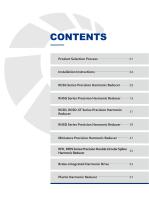
RCSG Series Precision Harmonic Reducer-----09 RHSG Series Precision Harmonic Reducer-----19 RCSD, RCSD-ST Series Precision Harmonic ^ RHSD Series Precision Harmonic Reducer-----39 Miniature Precision Harmonic Reducer-------47 RFR, RFRS Series Precision Double Circular Spline 5 5 Harmonic Reducer
Open the catalog to page 3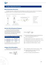
The Wave Generator includes both the self-aligning cross slider structure and the non-self-aligning integrated structure. For more details, please refer to the outline drawings of each series. Service Life of Harmonic Reducer The service life of a Harmonic Reducer mainly depends on the service life of Wave Generatorflexible bearing and the fatigue life of the Flexspline. The fatigue life of Flexspline isdetermined by the bendingcycles. Service Life of Wave Generator Flexible Bearing Note:The table data represents the service life under rated operating conditions (e.g., rated rotation speed, rated...
Open the catalog to page 4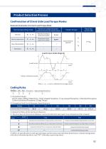
Product Selection Process Confirmation of Client-Side Load Torque Modes Relevant Parameters For Each Load Torque Mode © Refers to specifications with special shape, performance and interface dimensions. A blank designation indicates a standard product, and "SP" indicates a special product.
Open the catalog to page 5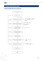
Product Model Selection Flowchart
Open the catalog to page 6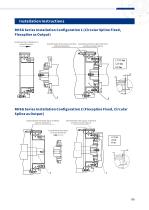
RHSG Series Installation Configuration 1 (Circular Spline Fixed, Flexspline as Output) Install Harmonic Reducer in Arrow Direction
Open the catalog to page 7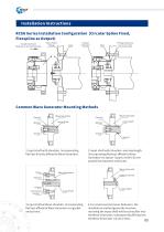
Common Wave Generator Mounting Methods 05 3. Input shaft without shoulder (incorporating flat key) affixed to Wave Generator via gasket and screws. 4.Forsmall-size Harmonic Reducers, the installation method generally involves inserting the input shaft without shoulder into the Wave Generator, subsequently affixing it to the Wave Generator via setscrews.
Open the catalog to page 8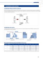
After assembling and positioning the Circular Spline and Flexspline, proceed with Wave Generator installation. Incorrect assembly procedures may lead to gear tooth misalignment, potentially causing tooth surface damage and other related complications. To fully leverage the excellent performance inherent in component type Harmonic Reducers, please ensure the installation accuracy as follows. Note: Dimensions b and c pertain to the Wave Generator, with parenthetical values indicating those for the Cross Slider Type (Type II) Wave Generator.
Open the catalog to page 9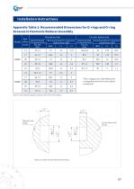
Note: In case of doubt, please contact us for further clarification.
Open the catalog to page 10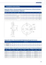
Installation Instructions Appendix Table 2: Recommended Gasket Dimensions of Hub for RCSG-I and RHSG-I Series Harmonic Reducers Appendix Table 3: Recommended Tightening Torque for Screws
Open the catalog to page 11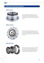
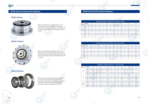
RCSG-I is standard cup-shaped structure. The input shaft is directly matched with the Wave Generator's inner bore by a flat key. Generally, the Circular Spline is fixed, and the Flexspline sets as output. RCSG-II is standard cup-shaped structure. The input shaft is connected to the Wave Generator's inner bore through an Oldham coupling. Generally, the Circular Spline is fixed, and the Flexspline sets as output. RCSG-I 11 is composed of three parts: a Flexspline, a Circular Spline, and a Wave Generator. The Flexspline is standard cup-shaped structure. The input shaft is directly matched with the...
Open the catalog to page 12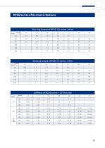
Starting torque of RCSG-I/11 series /cN-m Starting torque of RCSG-III series /cN-m Stiffness of RCSG series xlO4
Open the catalog to page 13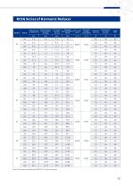
Note:The maximum backlash of RCSG-II islOarcsec more.
Open the catalog to page 15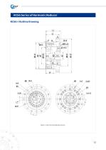
RCSG Series of Harmonic Reducer
Open the catalog to page 16
RCSG-I Dimension Table ^^^Nlodel
Open the catalog to page 17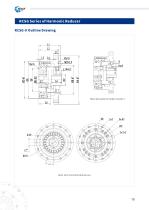
RCSG Series of Harmonic Reducer
Open the catalog to page 18
RCSG-II Dimension Table a°
Open the catalog to page 19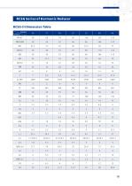
RCSG-III Dimension Table ^^^^Model
Open the catalog to page 21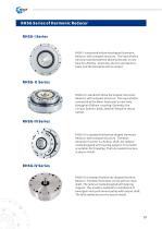
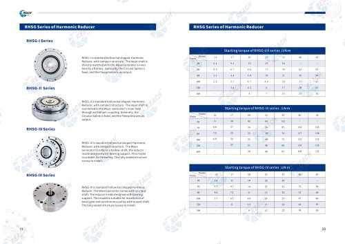
RHSG-I isstandard hollow hatshaped Harmonic Reducer, with com pact structure. The input shaft is directly matched with the Wave Generator's inner bore by a flat key. Generally, the Circular Spline is fixed, and the Flexspline sets as output. RHSG-II isstandard hollow hatshaped Harmonic Reducer, with com pact structure. The input shaft is connected to the Wave Generator's inner hole through an Oldham coupling. Generally, the Circular Spline is fixed, and the Flexspline sets as output. RHSG-III isstandard hollow hat shaped Harmonic Reducer, with compactstructure. The Wave Generator's center is...
Open the catalog to page 22
Starting torque of RHSG-I/II series /cN-m
Open the catalog to page 23
Note:The maximum backlash of RHSG-II islOarcsec more than thatin the table.
Open the catalog to page 25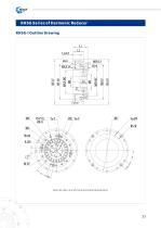
RHSG Series of Harmonic Reducer
Open the catalog to page 26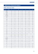
RHSG-I Dimension Table ~~——Model Symbol
Open the catalog to page 27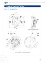
RHSG-II Outline Drawing
Open the catalog to page 28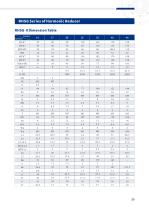
RHSG- II Dimension Table ^^^^Model
Open the catalog to page 29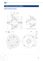
RHSG Series of Harmonic Reducer
Open the catalog to page 30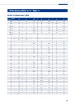
RHSG-III Dimension Table a°
Open the catalog to page 31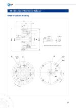
RHSG Series of Harmonic Reducer
Open the catalog to page 32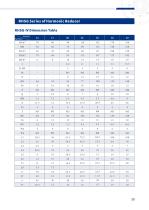
RHSG Series of Harmonic ReducerRHSG-IV Dimension Table ^^^^Model
Open the catalog to page 33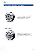
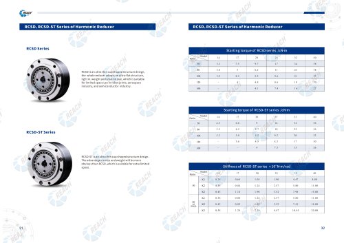
RCSD is an ultra thin cup shaped structure design, the whole reducer adopts an ultra-flat structure, light in weight and small in size, which is suitable for limited space use in robot joints, aerospace industry, and semiconductor industry. RCSD-ST is an ultra thin cup shaped structure design. The advantages in size and weight will be more obviousthan RCSD, which is suitable forextra limited space.
Open the catalog to page 34
Startingtorque of RCSD series /cN-m Stiffness of RCSD-ST series xl04N-m/rad
Open the catalog to page 35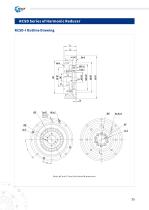
RCSD Series of Harmonic Reducer
Open the catalog to page 38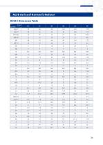
RCSD-I Dimension Table Symbol
Open the catalog to page 39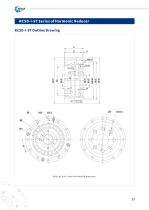
RCSD-I-ST Series of Harmonic Reducer
Open the catalog to page 40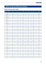
RCSD-I-ST Dimension Table Sym bol
Open the catalog to page 41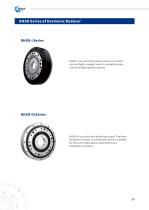
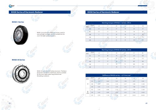
RHSD-I isan ultra thin hollow structure, small in size and light in weight, which is suitable for the use in the tight-space occasions. RHSD-I 11 isan ultra thin hollow structure.The Wave Generator's center is a shaft hole, which is suitable forthe use in tight-space requirement and threading occasions.
Open the catalog to page 42
Starting torque of RHSD-
Open the catalog to page 43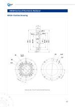
RHSD Series of Harmonic Reducer
Open the catalog to page 46
RHSD-I Dimension Table Model
Open the catalog to page 47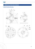
RHSD Series of Harmonic Reducer
Open the catalog to page 48
RHSD-III Dimension Table Sym bol
Open the catalog to page 49
Stiffness of RCS-mini series X10
Open the catalog to page 50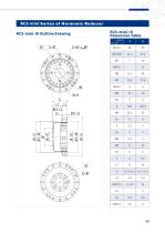
RCS-mini Series of Harmonic ReducerRCS-mini-lll Outline Drawing RCS-mini-lll Dimension Table
Open the catalog to page 51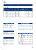
Stiffness of RHS-mini series X10
Open the catalog to page 52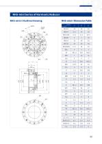
RHS-mini Series of Harmonic Reducer RHS-mini-l Outline Drawing
Open the catalog to page 53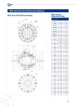
RHS-mini-lll Dimension Table
Open the catalog to page 54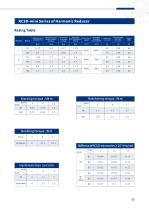
RatingTable Starting torque /cN-m
Open the catalog to page 55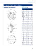
RHSD-mini-l Outline Drawing RHSD-mini-l Dimension Table Symbol^^^
Open the catalog to page 57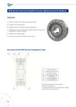
• Ultra thin Structure for high-torque applications; • Composed of 4 components; • Flexspline with thin-walled cylindrical geometry; • An additional Circular Spline (matching Flexspline tooth count) integrated foroutputcoupling; • Compactand simpledesign; • Superior positional and rotational accuracies. Distinction between CircularSpline D and CircularSplineS: The outer chamfer of Circular Spline D is larger than that of CircularSplineS.
Open the catalog to page 58All Reach Machinery Co.,Ltd. catalogs and technical brochures
 Electromagnetic Brakes
8 Pages
 Electromagnetic Brakes
14 Pages
 Couplings Reach@GS
59 Pages
 Couplings GR
59 Pages
 REACH 22
1 Page
 REACH 21
1 Page
 REACH 20
1 Page
 REACH 19
2 Pages
 REACH 18
1 Page
 REACH 17
1 Page
 REACH 16
1 Page
 REACH 15
1 Page
 REC
REC9 Pages
 RDC
RDC4 Pages
 RGE-GR
3 Pages
 REACH 13
1 Page
 REACH 12
1 Page
 REACH 11
1 Page
 REACH 07
2 Pages
 REACH 06
2 Pages
 REACH 05
2 Pages
 REACH 04
2 Pages
 REACH 03
2 Pages
 REACH 01
2 Pages
 REB18 Square hub
1 Page
 REACH 14
2 Pages
 REACH 02
1 Page


- Reach Machinery coaxial gear reducer
- Precision gearhead
- Compact gearhead
- Solid-shaft gearhead
- Flexible coupling
- Shaft shaft coupling
- Reach Machinery hollow-shaft gear reducer
- Reach Machinery friction brake
- Transmission gearhead
- Shaft gearhead
- Dual-stage gearbox
- High-performance gearhead
- Low-noise gearhead
- Low-backlash gearhead
- Torque coupling
- High-precision gearhead
- High-torque gearhead
- Reach Machinery robot gear reducer
- Transmission coupling
- Rigid coupling