Stand alonte single or dual channel digital compressor
1 /9Pages

Stand alonte single or dual channel digital compressor
1 /9Pages
Catalog excerpts
rakon Digital pulse cumpicssiuM muuuic CI F06 Expander and Compressor To make an enquiry please email: [email protected] Product description CI F06 unit includes a digital pulse expander and the matched digital pulse compressor housed in a single unit. The pulse expander generates a frequency coded pulse, also called a chirp. Pulse output is IF analog. The pulse compressor performs matched filtering of the expanded chirp. Compressor pulse input and output are IF analog. CI F06 may be customized to generate and match linear or non linear chirps. CI F06 may be used as a replacement of existing SAW based pulse expander and/or compressor to overcome device obsolescence or enhance RADAR performances. CI F06 behavior and performances are reproducible from one unit to the other. No matching is needed. CI F06 may be used with CI F04/05 to get multiple compressor channels, also without matching required from one unit to the other. Rakon will customize pulse expander chirp and pulse compression filter according to the characteristics requested by the customer (Chirp duration, bandwidth, compressed pulse width, chirp slope ...). The unit is provided with FPGA firmware loaded, including pulse expander waveforms and pulse compression filter. Features Single channel pulse expander unit Օ Single channel pulse compressor unit IF analog I/Os Օ 2 selectable waveforms for expander and compressor High precision clock Օ BITE function High BxT compression gain 1 3 10 Bandwidth B [MHz) Applications Օ SAW based pulse compression RADARS upgrade August 25th, 2011 CI F06 Expander and Compressor Revision A1 1 / 9 www.rakon.com
Open the catalog to page 1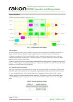
rai on L/igital CI F06 Expander and Compressor Technical description CI F06 functional block diagram is featured on Fig. 1. FPGA WFMSel_E Wavefo rm selection ^ Trigger Stored Timing Wa veforms Out_E Fig. 1 : CI F06 functional block diagram Unit description. The internal low noise system clock is locked on an external clock (derived from the RADAR system clock). For proper operation, the clock should be a good quality clock, with a low phase noise close to the carrier. CI F06 unit is provided with FPGA firmware loaded. Functions, and channels specifications (time dispersion, compressed pulse width,...
Open the catalog to page 2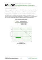
rakon L/igital CI F06 Expander and Compressor Pulse compressor channel description. Input chirps are filtered (anti-aliasing filter), sampled and down-converted to baseband. I and Q baseband data are processed by FIR filters whose coefficients are matched with the expander chirp characteristics. Digital baseband I/Q compressed pulse is then up-converted to carrier frequency and converted into analog signal. As inputs and outputs are IF analog signals, CI F06 is well suited to upgrade SAW based pulse compression Radars. For better compatibility with old SAW based subsystems, an adjustable additional...
Open the catalog to page 3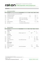
rakon Digital pulse tumpicssiuM muuuic CI F06 Expander and Compressor Spcifications 1 Environmental conditions Line Parameter Test Condition Min. Typ. Max. Unit Procdures and conditions refer to MIL-STD-810G 1.1 Temperature operating -25 +60 °C 1.2 Temperature storage -40 +85 °C 1.3 Humidity operating @ 30 °C, (non condensing) 95 % RH 1.4 Shock 11 ms, 3 axes, 2 dir, half sine pulse 30 g 1.5 Random Vibration 20 to 500 Hz, 3 axes 0.1 g2/Hz 1.6 EMI - EMC In accordance with MIL-STD 461 E 2 Electrical Interface Line Parameter Test Condition Min. Typ. Max. Unit Power supply 2.1 Voltage 11 26 V 2.2...
Open the catalog to page 4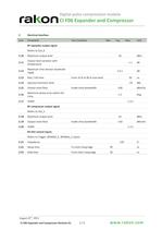
rai on Digital pulse tumpicssiuM muuuic CI F06 Expander and Compressor 2 Electrical Interface Line Parameter Test Condition Min. Typ. Max. Unit RF expander output signal Refers to Out_E 2.10 Maximum output level 10 dBm 2.11 Output level variation with ± 1 dB temperature 2.12 Maximum time domain amplitude ± 0.1 dB ripple 2.13 Rise / Fall time From 10 % to 90 % max level 50 ns 2.14 Spurious harmonie level -70 dBe 2.15 Output noise floor Inside ehirp bandwidth -140 dBm/Hz 2.16 Maximum phase error within the ehirp ± 2 Deg. 2.17 VSWR 1.3:1 RF compressor output signal Refers to Out_C 2.18 Maximum output...
Open the catalog to page 5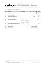
rai on L/IgllCIl CI F06 Expander and Compressor 3 CI F06 expander opration Performances Line Parameter Test Condition Min. Typ. Max. Unit 3.1 Center frequency (F0) 100 -B/2 MHz 3.2 Maximum bandwidth (B) 45 MHz 3.3 Maximum time dispersion (T) 1000 Us 3.4 Minimal expander delay (TE) Measured from first Clock rising edge after Trigger low to high transition, to the center of the output chirp. T/2 + 0.3 Us 3.5 Maximal additional expander delay (TE) Measured from first Clock rising edge after Trigger low to high transition, to the center of the output chirp. 1 ms 3.6 Modulation slope Up-chirp / Down-chirp...
Open the catalog to page 6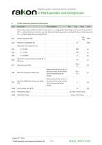
rakon L/IgllCIl CI F06 Expander and Compressor 4 CI F06 compressor opration Performances Line Parameter Test Condition Min. Typ. Max. Unit Note: Values given bellow are typical values given as a rough guide. Depending on the required parameters (B, T,...) other limitations may rise, e.g. side lobe levels highly depends on bandwidth (B) and time dispersion (T), i.3dB highly depends on bandwidth (B), ... 4.1 Center frequency (F0) 100 - B/2 MHz 4.2 Maximum bandwidth (B) 45 MHz Maximum time dispersion (T) 4.3 B < 3 MHz 950 Us 4.4 B < 7 MHz 170 Us 4.5 B < 20 MHz 17 Us 4.6 Minimum compressed pulse...
Open the catalog to page 7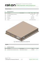
Digital pulse cumpicssiuM muuuic CI F06 Expander and Compressor Mechanical features 5 Mechanical features Line Parameter Test Condition Min. Typ. Max. Unit 5.1 Unit outline without connectors 175 x 152 x 23.5 mm3 5.2 Unit weight < 0.6 kg 5.3 Material AG4.5MC 5.4 Treatment Ni15 / Zn1 5.5 Screws A4-70 stainless steel Fig. 3 : Mechanical drawing (connectors position TBC) Reliability 6 Reliability information Line Parameter Test Condition Value Unit 6.1 Estimated mean time between failure FIDES 2004, 30°C ambient > 250 000 H August 25th, 2011 CI F06 Expander and Compressor Revision A1 8 / 9 www .rakon.com...
Open the catalog to page 8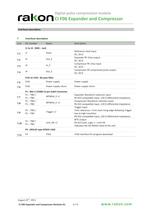
rakon L/igitai CI F06 Expander and Compressor Interfaces description 7 Interfaces description Line Pin number Name Description J1 to J4 : SMA - Jack 7.1 J1 Clock Reference clock input AC, 50 Q 7.2 J2 Out_E Expander RF chirp output AC, 50 Q 7.3 J3 In_C Compressor RF chirp input AC, 50 Q 7.4 J4 Out_C Compressor RF compressed pulse output AC, 50 Q FL01 to FL02 : By-pass filter 7.5 FL01 Power supply Power supply 7.6 FL02 Power supply return Power supply return P1 : MIL-C-24308 15-pin SubD Connector P1 - TBD / WFMSel_E +/- Expander Waveform selection input 7.7 P1 - TBD RS-422 compatible input, 120...
Open the catalog to page 9All Rakon catalogs and technical brochures
 RTF 1610 RevB
1 Page
 RSX-10v1
1 Page
 RSX-8 v1
1 Page
 LNO100 A4
9 Pages
 RXO7050R
7 Pages
 CIE03
CIE0311 Pages
 CIF0405
8 Pages
 CIF06
CIF069 Pages
 MO G01
3 Pages
 RFPO65
2 Pages
 RFPO60
2 Pages
 RFPO55
2 Pages
 RFPO50
2 Pages
 RFPO45
2 Pages
 RFPO40
2 Pages
 ROX2522S4
2 Pages
 ROX2525S4
2 Pages
 ROX2525T5
2 Pages
 ROX3627T3
2 Pages
 ROX3827T3
2 Pages
 ROX5242T2
2 Pages
 ROX5252T2
2 Pages
 ROX5252T1
2 Pages
 IT3200C
7 Pages
 IT2200J
7 Pages
 IT2200K
7 Pages
 IT2100F
2 Pages
 CFPT9050
9 Pages
 CFPT9000
12 Pages
 CFPT9300
9 Pages
 RFPT500
5 Pages
 RFPT400
5 Pages
 RPT5032N
2 Pages
 RPT7050N
2 Pages
 RPT5032P
2 Pages
 RPT7050P
2 Pages
 RPT5032J
2 Pages
 RPT7050J
2 Pages
 RPT5032A
2 Pages
 RPT7050A
2 Pages
 RHF7050A
2 Pages
 RHT1490J
2 Pages
 RHT1490A
2 Pages
 RFPT100
2 Pages
 RPT7050G
3 Pages
 RFPT200
7 Pages
 RFPT700
6 Pages
 RPT7050D
2 Pages
 RVX1490M
7 Pages
 RVX7050R
8 Pages
 RVX7050P
8 Pages
 RVX7050M
9 Pages
 RVX5032R
8 Pages
 RVX5032P
8 Pages
 RVX5032M
7 Pages
 RVX2520P
1 Page
 RVX2520R
1 Page
 RVG1490L
2 Pages
 RCV2520Q
1 Page
 RXO7050P
7 Pages
 RXO7050M
9 Pages
 RXO5032R
7 Pages
 RXO5032P
7 Pages
 RXO5032M
10 Pages
 RXO2520P
1 Page
 RXO2520R
1 Page
 RXG1490L
2 Pages
 RCX2520Q
1 Page
 QEN49
QEN494 Pages
 QEN55
QEN554 Pages
 RK115
RK1152 Pages
 CFPX3750
7 Pages
 CFPX3758
7 Pages
 CFPX3000
7 Pages
 RHC-49US
5 Pages
 RSX-5
RSX-55 Pages
 Synchronous Ethernet
2 Pages
 Base Station Solutions
2 Pages
 GNSS Based Synchronisation
2 Pages
 Small Cell Solutions
2 Pages
 The Internet of Things
2 Pages
 GNSS Positioning Solutions
2 Pages
 RGX-3
RGX-37 Pages
 RSX-8
RSX-810 Pages
 RSX10
RSX105 Pages
 RSX-11
5 Pages
 RSX1612
7 Pages
 RXT2520AT
6 Pages
 RXT2016AT
6 Pages
 RTF3215
1 Page
 RK 409
7 Pages
 RK 407
2 Pages
 CIF07
CIF076 Pages
 BASE STATION FACT SHEET
2 Pages
 DEFENSE FACT SHEET
2 Pages
 SMALL CELLS FACT SHEET
2 Pages
 Space OCXO series RK 408
9 Pages
 Crystal filters FTF 1
2 Pages
 Rakon XO QEN79
4 Pages
 ULN USO Module Assembly
5 Pages


- Crystal oscillator
- Electronic oscillator
- Surface-mount oscillator
- Frequency oscillator
- OCXO oscillator
- Crystal resonator
- SMD oscillator
- Oscillator for telecom applications
- XO oscillator
- Voltage oscillator
- Phase oscillator
- Power oscillator
- Low-noise oscillator
- Clock oscillator
- Oscillator with connector
- Automated oscillator
- Plug-in oscillator
- High-stability oscillator
- VCO oscillator
- SAW oscillator