RFPT200
1 /7Pages

RFPT200
1 /7Pages
Catalog excerpts
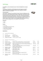
rakon The CHARON is a SPI controlled high accuracy TCXO with embedded timer and alarm function. The Charon is a high stability 7x5 SMD Digitally Controlled Temperature Controlled Crystal Oscillator (DCTCXO) designed and specified to bring together the highest stability TCXO performance with digital frequency control, separate low frequency output, timer and alarm functionality. jyjjduct description Serial Peripheral Interface (SPI) controlled high accuracy TCXO with embedded timer and alarm function. Using Rakon's advanced Pluto™ analogue frequency compensation system, the DCTCXO achieves unrivalled frequency stability. A custom ASIC, Charon (Pluto's moon) has been designed to closely interface with the Pluto™ ASIC to provide the extra enhanced functionality in a miniature 7x5 SMD package. In addition to market leading stability the Charon device features integrated timing and control functions. A low frequency timing pulse is derived from a programmable division ratio of the high stability oscillator. This drives the onboard 32 bit timer, which coupled to a 32 bit programmable comparator and alarm circuitry, enables a system to enter a low power standby mode and be woken at a precise time in the future. All digital control is via a standard 4-wire SPI interface. Applications • Military • Other Features • 32 bit timer • 32 bit comparator with alarm output • Low frequency timing pulse • Digital frequency adjustment • Low power standby mode 1.2 RoHS compliant Available on request 1.3 Package size available 7.0 mm x 5.0 mm x 2.8 mm 2.0 FREQUENCY CHARACTERISTICS Line Parameter Test Condition Frequency range Frequency calibration Frequency stability over temperature Temperature range Stability vs. supply voltage changes Stability vs. load changes Long term stability Long term stability Drift due to reflow soldering Frequency range available depends on output type (Note 1) At 25°C at mid-range of DAC, reference nominal frequency Reference to (Fmax+Fmin)/2. Max ±0.15 ppm only available over -20°C to 70°C (Note 2) The operating temperature range over which the frequency stability is measured (Note 3) ±5% variation in supply voltage. Nominal value ±0.1 ppm ±10% variation in load. Nominal value ±0.1 ppm At 25°C, first year. Nominal value ±1 ppm At 25°C, 10 years predicted, including first year. Nominal value ±3 ppm At 25°C, at mid-range of DAC, 24 hours after reflow. Unit MHz ppm ppm °C ppm ppm ppm ppm ppm
Open the catalog to page 1
3.0 POWER SUPPLY Line Parameter Test Condition 3.1 Supply voltage Normally specified as nominal (Vcc) ±5%. 3.2 Supply current 3.3V, load 15pF (min.@ 10MHz, max.@ 40MHz). 3.3 Supply current RF output disabled (min.@ 10MHz, max.@ 40MHz). Unit V mA mA 4.0 HCMOS OSCILLATOR OUTPUT Line Parameter 4.2 Output voltage level high 4.4 Rise and fall times Test Condition HCMOS 10% to 90% of Voh-Vol. Nominal value 6 ns Measured at 50% Vcc Normally specified at CL±10%. Nominal value 15 pF Unit %Vcc %Vcc ns % pF CLIPPED SINEWAVE OSCILLATOR OUTPUT Parameter Output waveform Output voltage...
Open the catalog to page 2
LF TIMING PULSE: PULSE PERIOD 9.0 Line Parameter 9.1 LF pulse period 9.2 LF pulse period Test Condition Sync counter setting. User programmable register. Sync ratio at power up: 4096 LF timing pulse period = oscillator period * ripple * sync Value Unit LF TIMING PULSE: ENABLE SETTING Parameter LF output off LF output on Test Condition SPI or bonded in paralled to RF enable SPI or bonded in paralled to RF enable Value Unit 11.0 COUNTER Line Parameter 11.1 32 bit timer Test Condition Continuous count of LF, reset on power up, read via SPI Default: 0. Maximum: 232-1 LF counts (232-1)...
Open the catalog to page 3
16.0 PIN CONNECTIONS Line Parameter 16.1 Pin 1 16.2 Pin 2 16.3 Pin 3 16.4 Pin 4 16.5 Pin 5 16.6 Pin 6 16.7 Pin 7 16.8 Pin 8 16.9 Pin 9 16.10 Pin 10 16.11 Pin 11 16.12 Pin 12 16.13 Note Description SPI-CLK (SCLK) SPI-IN (SDI) SPI-OUT (SDO) GND +Vs* RF out ALARM LF out RF & LF enable Supply, +Vs DAC_OUT/VCXO* SPI-EN (SS enable low) * = No connection required, monitor points used during manufacture 18.0 MANUFACTURING INFORMATION Line Parameter 18.1 Solderability 18.2 Reflow 18.3 Materials Description MIL-STD-202, method 208, category 3 Solder reflow processes as per attached profile. When soldering,...
Open the catalog to page 4
SIDE VIEW NOTE: Pin connections are detailed in the specificationBOTTOM VIEW TITLE: RFPT200 MODEL OUTLINE DRAWING FILENAME: RFPT200_MD REVISION: A Millimeters [inch] rakon ©2009 Rakon Limited
Open the catalog to page 5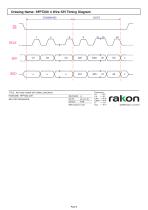
RFPT200 4 WIRE SPI TIMING DIAGRAM Millimeters [mchj
Open the catalog to page 6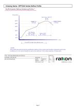
* NOTE: This profile was used during the qualification testing of the product and therefore represents worst case conditions. It is not recommended for use by the customer in the actual assembly of these parts. TITLE: RFPT200 SERIES REFLOW PROFILE FILENAME: RFPT200_RF RELATED DRAWINGS: SCALE: NTS Millimeters [inch] rakon ©2009 Rakon Limited
Open the catalog to page 7All Rakon catalogs and technical brochures
 RTF 1610 RevB
1 Page
 RSX-10v1
1 Page
 RSX-8 v1
1 Page
 LNO100 A4
9 Pages
 RXO7050R
7 Pages
 CIE03
CIE0311 Pages
 CIF0405
8 Pages
 CIF06
CIF069 Pages
 MO G01
3 Pages
 RFPO65
2 Pages
 RFPO60
2 Pages
 RFPO55
2 Pages
 RFPO50
2 Pages
 RFPO45
2 Pages
 RFPO40
2 Pages
 ROX2522S4
2 Pages
 ROX2525S4
2 Pages
 ROX2525T5
2 Pages
 ROX3627T3
2 Pages
 ROX3827T3
2 Pages
 ROX5242T2
2 Pages
 ROX5252T2
2 Pages
 ROX5252T1
2 Pages
 IT3200C
7 Pages
 IT2200J
7 Pages
 IT2200K
7 Pages
 IT2100F
2 Pages
 CFPT9050
9 Pages
 CFPT9000
12 Pages
 CFPT9300
9 Pages
 RFPT500
5 Pages
 RFPT400
5 Pages
 RPT5032N
2 Pages
 RPT7050N
2 Pages
 RPT5032P
2 Pages
 RPT7050P
2 Pages
 RPT5032J
2 Pages
 RPT7050J
2 Pages
 RPT5032A
2 Pages
 RPT7050A
2 Pages
 RHF7050A
2 Pages
 RHT1490J
2 Pages
 RHT1490A
2 Pages
 RFPT100
2 Pages
 RPT7050G
3 Pages
 RFPT700
6 Pages
 RPT7050D
2 Pages
 RVX1490M
7 Pages
 RVX7050R
8 Pages
 RVX7050P
8 Pages
 RVX7050M
9 Pages
 RVX5032R
8 Pages
 RVX5032P
8 Pages
 RVX5032M
7 Pages
 RVX2520P
1 Page
 RVX2520R
1 Page
 RVG1490L
2 Pages
 RCV2520Q
1 Page
 RXO7050P
7 Pages
 RXO7050M
9 Pages
 RXO5032R
7 Pages
 RXO5032P
7 Pages
 RXO5032M
10 Pages
 RXO2520P
1 Page
 RXO2520R
1 Page
 RXG1490L
2 Pages
 RCX2520Q
1 Page
 QEN49
QEN494 Pages
 QEN55
QEN554 Pages
 RK115
RK1152 Pages
 CFPX3750
7 Pages
 CFPX3758
7 Pages
 CFPX3000
7 Pages
 RHC-49US
5 Pages
 RSX-5
RSX-55 Pages
 Synchronous Ethernet
2 Pages
 Base Station Solutions
2 Pages
 GNSS Based Synchronisation
2 Pages
 Small Cell Solutions
2 Pages
 The Internet of Things
2 Pages
 GNSS Positioning Solutions
2 Pages
 RGX-3
RGX-37 Pages
 RSX-8
RSX-810 Pages
 RSX10
RSX105 Pages
 RSX-11
5 Pages
 RSX1612
7 Pages
 RXT2520AT
6 Pages
 RXT2016AT
6 Pages
 RTF3215
1 Page
 RK 409
7 Pages
 RK 407
2 Pages
 CIF07
CIF076 Pages
 BASE STATION FACT SHEET
2 Pages
 DEFENSE FACT SHEET
2 Pages
 SMALL CELLS FACT SHEET
2 Pages
 Space OCXO series RK 408
9 Pages
 Crystal filters FTF 1
2 Pages
 Rakon XO QEN79
4 Pages
 ULN USO Module Assembly
5 Pages


- Electronic oscillator
- Surface-mount oscillator
- Frequency oscillator
- OCXO oscillator
- Crystal resonator
- SMD oscillator
- Oscillator for telecom applications
- XO oscillator
- Voltage oscillator
- Phase oscillator
- Power oscillator
- Low-noise oscillator
- Clock oscillator
- Oscillator with connector
- Automated oscillator
- Plug-in oscillator
- High-stability oscillator
- VCO oscillator
- SAW oscillator