IT2200K
1 /7Pages

IT2200K
1 /7Pages
Catalog excerpts
rakon gu-wiemperature Compensated Crystal Oscillators SMD TCXO using analogue ASIC for compensation and an optional Enable/Disable pin for efficient power management. aSduct description The I(V)T2200K employs an analogue ASIC for the oscillator and a high order temperature compensation circuit in a 2.5 x 2.0 mm size package. The device can be placed in power down mode through a single input pin. During standard operation, power consumption is minimized by operating down to a supply voltage of 1.8V. The I(V)T2200K's high stability, low power consumption, small footprint and powerful compensation method makes it a TCXO ideally suited for demanding GPS mobile applications. Applications • GPS • Smartphone • PND • Consumer • Communications • Wi-Fi • WiMAX/W-LAN Features • Frequency slope and perturbation specifications can be customized to the application requirement • Excellent phase noise performance • Standard temperature stability choices are ±0.5ppm, ±1ppm, ±1.5ppm and ±2.5ppm over wide temperature ranges Specifications 1.4 Rakon part number Value Unit Line Parameter over temperature 2.6 Frequency slope voltage variations 2.9 Sensitivity to load variations 2.10 Long term stability Test Condition Offset from nominal frequency measured at 25°C±2°C Two consecutive reflows as per attached profile after 1 hour recovery at 25°C The operating temperature range over which the frequency stability is measured Referenced to the midpoint between minimum and maximum frequency value over the specified temperature range. Control voltage set to midpoint of control voltage (Note 1) Minimum of 1 frequency reading every 2°C over the operating temperature range (Note 1) Frequency change after reciprocal temperature ramped over the operating range. Frequency measured before and after at 25°C Supply voltage varied ±5% at 25°C ±10% load change at 25°C (Note 2) Frequency drift over 1 year at 25°C
Open the catalog to page 1
Line Parameter Test Condition Nominal supply voltage range At maximum supply voltage (Note 2) Value Unit CONTROL VOLTAGE(VCO) Parameter Test Condition Control voltage range Control voltage range Frequency tuning The nominal control voltage value is midway between the minimum and maximum. Voltage control should not exceed the supply voltage +0.2 V or GND. Supply voltage £2.3 V. The nominal control voltage value is midway between the minimum and maximum. Voltage control should not exceed the supply voltage +0.2 V or GND. Supply voltage >2.3 V. Frequency shift from minimum to maximum control...
Open the catalog to page 2
Line Parameter Description Half sine-wave acceleration of 3000g peak amplitude. Duration: 0.3ms, Velocity: 12.3ft/s [MIL-STD-202 M213] (Note 4) 1000 hours at 85°C, 85% relative humidity. Biased. [MIL-STD-202 M106g] (Note 4) 1000 temperature cycles, where each cycle consists of a 25 minutes soak time at -40°C followed by a 25 minute soak time at 85°C, with a 60 second maximum transition time between temperatures. Air to air transition. [JESD22 METHOD JA-104C] (Note 4) 10g peak acceleration for 20 minutes. 12 cycles in each of 3 orientations. Test from 10-2000Hz [JESD22-B103-B] (Note 4) -40...
Open the catalog to page 3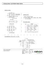
MODEL OUTLINE MARKING NOTE [ XXXX ] = Frequency in MHz. e.g.: 8AOO = 8.00MHz, 19A2 = 19.2MHz, 100A= 100MHz (A = IT/IVT2200K) FRONT VIEW NOTE: * Connect to VCC or floating to enable TCXO RECOMMENDED 4 PAD LAYOUT - TOP VIEW TITLE: l(V)T2200K MODEL RELATED DRAWINGS: Recommended No Tracks Including Plains Under Device -Output to Circuit External AC-Coupling Capacitor > InF TOLERANCES: XX = X.X = ±0.2 X.XX = ±0.10 X.XXX = ±0.05 X° = FI ole = rakon © 2013 Rakon Limited
Open the catalog to page 4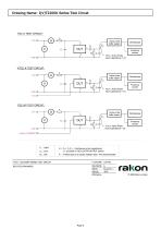
TITLE: l(V)T2200K SERIES TEST CIRCUIT RELATED DRAWINGS: SCALE: NTS rakon © 2009 Rakon Limited
Open the catalog to page 5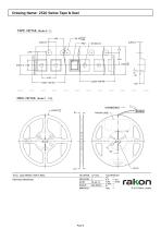
TAPE DETAIL (Scale 5 :1) 1.25 ■ REEL DETAIL (Scale 1 : 2.5) TITLE: 2520 SERIES TAPE & REEL RELATED DRAWINGS: SCALE:_See Above TOLERANCES: XX = X.X = ±0.1 X.XX = ±0.05 X.XXX = X° = Hole = rakon © 2013 Rakon Limited
Open the catalog to page 6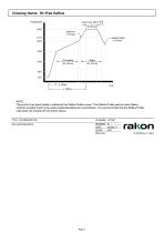
NOTE: The product has been tested to withstand the Reflow Profile shown. The Reflow Profile used to solder Rakon products is determined by the solder paste Manufacturer's specification. It is recommended that the Reflow Profile used does not exceed the one shown above. TITLE: Pb-FREE REFLOW RELATED DRAWINGS: SCALE: NTS rakon © 2009 Rakon Limited
Open the catalog to page 7All Rakon catalogs and technical brochures
 RTF 1610 RevB
1 Page
 RSX-10v1
1 Page
 RSX-8 v1
1 Page
 LNO100 A4
9 Pages
 RXO7050R
7 Pages
 CIE03
CIE0311 Pages
 CIF0405
8 Pages
 CIF06
CIF069 Pages
 MO G01
3 Pages
 RFPO65
2 Pages
 RFPO60
2 Pages
 RFPO55
2 Pages
 RFPO50
2 Pages
 RFPO45
2 Pages
 RFPO40
2 Pages
 ROX2522S4
2 Pages
 ROX2525S4
2 Pages
 ROX2525T5
2 Pages
 ROX3627T3
2 Pages
 ROX3827T3
2 Pages
 ROX5242T2
2 Pages
 ROX5252T2
2 Pages
 ROX5252T1
2 Pages
 IT3200C
7 Pages
 IT2200J
7 Pages
 IT2100F
2 Pages
 CFPT9050
9 Pages
 CFPT9000
12 Pages
 CFPT9300
9 Pages
 RFPT500
5 Pages
 RFPT400
5 Pages
 RPT5032N
2 Pages
 RPT7050N
2 Pages
 RPT5032P
2 Pages
 RPT7050P
2 Pages
 RPT5032J
2 Pages
 RPT7050J
2 Pages
 RPT5032A
2 Pages
 RPT7050A
2 Pages
 RHF7050A
2 Pages
 RHT1490J
2 Pages
 RHT1490A
2 Pages
 RFPT100
2 Pages
 RPT7050G
3 Pages
 RFPT200
7 Pages
 RFPT700
6 Pages
 RPT7050D
2 Pages
 RVX1490M
7 Pages
 RVX7050R
8 Pages
 RVX7050P
8 Pages
 RVX7050M
9 Pages
 RVX5032R
8 Pages
 RVX5032P
8 Pages
 RVX5032M
7 Pages
 RVX2520P
1 Page
 RVX2520R
1 Page
 RVG1490L
2 Pages
 RCV2520Q
1 Page
 RXO7050P
7 Pages
 RXO7050M
9 Pages
 RXO5032R
7 Pages
 RXO5032P
7 Pages
 RXO5032M
10 Pages
 RXO2520P
1 Page
 RXO2520R
1 Page
 RXG1490L
2 Pages
 RCX2520Q
1 Page
 QEN49
QEN494 Pages
 QEN55
QEN554 Pages
 RK115
RK1152 Pages
 CFPX3750
7 Pages
 CFPX3758
7 Pages
 CFPX3000
7 Pages
 RHC-49US
5 Pages
 RSX-5
RSX-55 Pages
 Synchronous Ethernet
2 Pages
 Base Station Solutions
2 Pages
 GNSS Based Synchronisation
2 Pages
 Small Cell Solutions
2 Pages
 The Internet of Things
2 Pages
 GNSS Positioning Solutions
2 Pages
 RGX-3
RGX-37 Pages
 RSX-8
RSX-810 Pages
 RSX10
RSX105 Pages
 RSX-11
5 Pages
 RSX1612
7 Pages
 RXT2520AT
6 Pages
 RXT2016AT
6 Pages
 RTF3215
1 Page
 RK 409
7 Pages
 RK 407
2 Pages
 CIF07
CIF076 Pages
 BASE STATION FACT SHEET
2 Pages
 DEFENSE FACT SHEET
2 Pages
 SMALL CELLS FACT SHEET
2 Pages
 Space OCXO series RK 408
9 Pages
 Crystal filters FTF 1
2 Pages
 Rakon XO QEN79
4 Pages
 ULN USO Module Assembly
5 Pages


- Electronic oscillator
- Surface-mount oscillator
- Frequency oscillator
- OCXO oscillator
- Crystal resonator
- SMD oscillator
- Oscillator for telecom applications
- XO oscillator
- Voltage oscillator
- Phase oscillator
- Power oscillator
- Low-noise oscillator
- Clock oscillator
- Oscillator with connector
- Automated oscillator
- Plug-in oscillator
- High-stability oscillator
- VCO oscillator
- SAW oscillator