CIE03
1 /11Pages

CIE03
1 /11Pages
Catalog excerpts
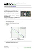
Digital pulse compression module To make an enquiry please email: [email protected] CI E03 is a digital dual pulse compression module, well suited for RADARS performance enhancement. Analog inputs and outputs make it an ideal replacement for SAW based pulse compression subsystems. Each of the two available channels may be configured as chirp expander or chirp compressor. All the pulse compression parameters are programmable (center frequency, bandwidth, time dispersion, modulation law, weighting function, etc.). CI E03 is provided with FPGA firmware, which will be configured by Rakon, based on customer requirements. • Digital pulse compression module • 2 concurrent channels : Expander or compressor for each channel • 2 x IF analog inputs, 2 x IF analog outputs • High precision clock, self sufficient or externally locked • BITE function • Low profile • High BxT compression gain • SAW based pulse compression RADARS upgrade
Open the catalog to page 1
Digital pulse compression module CI E03 Technical description CI E03 functional bloc diagram is featured on Fig. 2. DA C 250 MS PS 16 bits CPLD Superv ision BIT E IF Power Control VCFG N_ BOA RD_PD VINMA IN VINVCO Fig. 2 : CI E03 functional bloc diagram This module is specifically designed to upgrade existing SAW based pulse compression subsystems. Plugged on a specific carrier board, this module may upgrade many existing expanders and/or compressors. With a low size and low profile, it may be embedded in small form factors. This module is able to process on-the-fly 2 independent and concurrent...
Open the catalog to page 2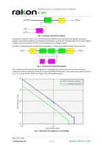
Digital pulse compression module TRIG Timing Fig. 3 : Expander channel bloc diagram Compressor, featured in Fig. 4, uses a FIR filter whose coefficients are matched to the expander waveform samples. Input data are preliminary translated into baseband, and then are translated again into IF signal. Digital IF signal is then presented to the DAC to be translated into an analog IF signal. For better compatibility with old SAW based subsystems, an adjustable additional delay may be inserted. RF IN Fig. 4 : Compressor channel bloc diagram Fig. 5 represents the maximum time dispersion vs. bandwidth...
Open the catalog to page 3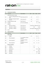
Digital pulse compression module
Open the catalog to page 4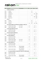
Digital pulse compression module
Open the catalog to page 5
Digital pulse compression module Logic low output voltage 1 Power dissipation highly depends on channels specifications. Typical figures are given as a rough guide. 2 Frequency should be divisible by 10 MHz
Open the catalog to page 6
Digital pulse compression module 3.0 Expander operation Performances 3 Some frequency values are not allowed. Center frequency should be related to the master clock by a fractional number. 4 Minimal delay depends slightly on the design. The typical figure is given as a rough guide.
Open the catalog to page 7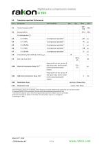
Digital pulse compression module 4.0 Compressor operation Performances 5 Some frequency values are not allowed. Center frequency should be related to the master clock by a fractional number. 6 Assuming 250 MHz FPGA processing, 3.5 points inside the compressed pulse width @ -3dB. 7 Side lobe level depends on B, T and other programmable parameters. Higher values are achievable. 8 Minimal delay depends slightly on the design. The typical figure is given as a rough guide. 9 Assuming B < 7 MHz.
Open the catalog to page 8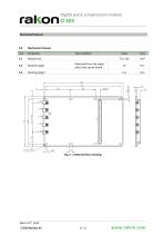
Digital pulse compression module Mechanical features
Open the catalog to page 9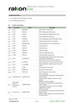
Digital pulse compression module Interfaces description J1 : Low profile 1.27 pitch, 2x50 pins connector J2 to J6 : MMCX jack connectors
Open the catalog to page 10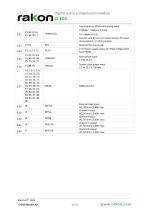
Digital pulse compression module
Open the catalog to page 11All Rakon catalogs and technical brochures
 RTF 1610 RevB
1 Page
 RSX-10v1
1 Page
 RSX-8 v1
1 Page
 LNO100 A4
9 Pages
 RXO7050R
7 Pages
 CIF0405
8 Pages
 CIF06
CIF069 Pages
 MO G01
3 Pages
 RFPO65
2 Pages
 RFPO60
2 Pages
 RFPO55
2 Pages
 RFPO50
2 Pages
 RFPO45
2 Pages
 RFPO40
2 Pages
 ROX2522S4
2 Pages
 ROX2525S4
2 Pages
 ROX2525T5
2 Pages
 ROX3627T3
2 Pages
 ROX3827T3
2 Pages
 ROX5242T2
2 Pages
 ROX5252T2
2 Pages
 ROX5252T1
2 Pages
 IT3200C
7 Pages
 IT2200J
7 Pages
 IT2200K
7 Pages
 IT2100F
2 Pages
 CFPT9050
9 Pages
 CFPT9000
12 Pages
 CFPT9300
9 Pages
 RFPT500
5 Pages
 RFPT400
5 Pages
 RPT5032N
2 Pages
 RPT7050N
2 Pages
 RPT5032P
2 Pages
 RPT7050P
2 Pages
 RPT5032J
2 Pages
 RPT7050J
2 Pages
 RPT5032A
2 Pages
 RPT7050A
2 Pages
 RHF7050A
2 Pages
 RHT1490J
2 Pages
 RHT1490A
2 Pages
 RFPT100
2 Pages
 RPT7050G
3 Pages
 RFPT200
7 Pages
 RFPT700
6 Pages
 RPT7050D
2 Pages
 RVX1490M
7 Pages
 RVX7050R
8 Pages
 RVX7050P
8 Pages
 RVX7050M
9 Pages
 RVX5032R
8 Pages
 RVX5032P
8 Pages
 RVX5032M
7 Pages
 RVX2520P
1 Page
 RVX2520R
1 Page
 RVG1490L
2 Pages
 RCV2520Q
1 Page
 RXO7050P
7 Pages
 RXO7050M
9 Pages
 RXO5032R
7 Pages
 RXO5032P
7 Pages
 RXO5032M
10 Pages
 RXO2520P
1 Page
 RXO2520R
1 Page
 RXG1490L
2 Pages
 RCX2520Q
1 Page
 QEN49
QEN494 Pages
 QEN55
QEN554 Pages
 RK115
RK1152 Pages
 CFPX3750
7 Pages
 CFPX3758
7 Pages
 CFPX3000
7 Pages
 RHC-49US
5 Pages
 RSX-5
RSX-55 Pages
 Synchronous Ethernet
2 Pages
 Base Station Solutions
2 Pages
 GNSS Based Synchronisation
2 Pages
 Small Cell Solutions
2 Pages
 The Internet of Things
2 Pages
 GNSS Positioning Solutions
2 Pages
 RGX-3
RGX-37 Pages
 RSX-8
RSX-810 Pages
 RSX10
RSX105 Pages
 RSX-11
5 Pages
 RSX1612
7 Pages
 RXT2520AT
6 Pages
 RXT2016AT
6 Pages
 RTF3215
1 Page
 RK 409
7 Pages
 RK 407
2 Pages
 CIF07
CIF076 Pages
 BASE STATION FACT SHEET
2 Pages
 DEFENSE FACT SHEET
2 Pages
 SMALL CELLS FACT SHEET
2 Pages
 Space OCXO series RK 408
9 Pages
 Crystal filters FTF 1
2 Pages
 Rakon XO QEN79
4 Pages
 ULN USO Module Assembly
5 Pages


- Crystal oscillator
- Electronic oscillator
- Surface-mount oscillator
- Frequency oscillator
- OCXO oscillator
- Crystal resonator
- SMD oscillator
- Oscillator for telecom applications
- XO oscillator
- Voltage oscillator
- Phase oscillator
- Power oscillator
- Low-noise oscillator
- Clock oscillator
- Oscillator with connector
- Automated oscillator
- Plug-in oscillator
- High-stability oscillator
- VCO oscillator
- SAW oscillator